正在加载图片...
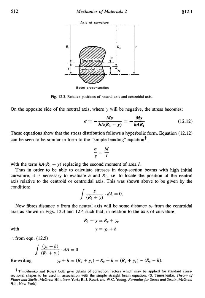
512 Mechanics of Materials 2 §12.1 Axis of curvature R Neutrai oxis Beam cross-section Fig.12.3.Relative positions of neutral axis and centroidal axis. On the opposite side of the neutral axis,where y will be negative,the stress becomes: My My =-hA(R1-y)hAR; (12.12) These equations show that the stress distribution follows a hyperbolic form.Equation(12.12) can be seen to be similar in form to the"simple bending"equationT. o M y=7 with the term hA(RI+y)replacing the second moment of area 1. Thus in order to be able to calculate stresses in deep-section beams with high initial curvature,it is necessary to evaluate h and Ri,i.e.to locate the position of the neutral axis relative to the centroid or centroidal axis.This was shown above to be given by the condition: y ·dA=0. J(R1+y) Now fibres distance y from the neutral axis will be some distance ye from the centroidal axis as shown in Figs.12.3 and 12.4 such that,in relation to the axis of curvature, R+y=Rc+yc with y=yc+h .'from egn.(12.5) (+h) (Rc yc) ·dA=0 Re-writing yc+h (Rc+yc)-Rc+h=(Rc +yc)-(Rc-h). Timoshenko and Roark both give details of correction factors which may be applied for standard cross- sectional shapes to be used in association with the simple straight beam equation.(S.Timoshenko.Theory of Plates and Shells,McGraw Hill,New York;R.J.Roark and W.C.Young,Formulas for Stress and Strain,McGraw Hill,New York).512 Mechanics of Materials 2 912.1 IRc -. 1-11 ! iY‘ Beam cross-section Fig. 12.3. Relative positions of neutral axis and centroidal axis. On the opposite side of the neutral axis, where y will be negative, the stress becomes: (12.12) These equations show that the stress distribution follows a hyperbolic form. Equation (12.12) can be seen to be similar in form to the “simple bending” equationt. aM __ - - YI with the term hA(R1 + y) replacing the second moment of area I. Thus in order to be able to calculate stresses in deep-section beams with high initial curvature, it is necessary to evaluate h and RI, Le. to locate the position of the neutral axis relative to the centroid or centroidal axis. This was shown above to be given by the condition: Now fibres distance y from the neutral axis will be some distance y, from the centroidal axis as shown in Figs. 12.3 and 12.4 such that, in relation to the axis of curvature, R1 + y = R, + yc with Y=Yc+h :. from eqn. (12.5) TTimoshenko and Roark both give details of correction factors which may be applied for standard crosssectional shapes to be used in association with the simple straight beam equation. (S. Timoshenko, Theory of Plares and Shells, McGraw Hill, New York; R. J. Roark and W.C. Young, Formulas for Stress and Strain, McGraw Hill, New York)