正在加载图片...
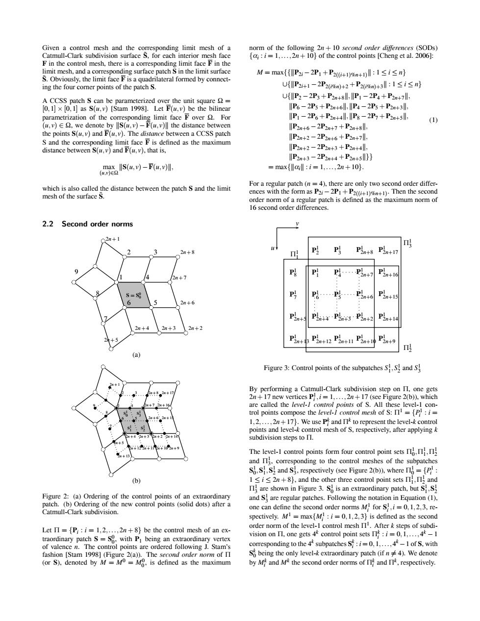
g如60aa五 2+2 1 点Isu,-fal 2.2 Second order norm ✉ Given a control mesh and the corresponding limit mesh of a Catmull-Clark subdivision surface S˜, for each interior mesh face F in the control mesh, there is a corresponding limit face F in the limit mesh, and a corresponding surface patch S in the limit surface S˜. Obviously, the limit face F is a quadrilateral formed by connecting the four corner points of the patch S. A CCSS patch S can be parameterized over the unit square Ω = [0,1] × [0,1] as S(u, v) [Stam 1998]. Let F(u, v) be the bilinear parametrization of the corresponding limit face F over Ω. For (u, v) ∈ Ω, we denote by S(u, v) − F(u, v) the distance between the points S(u, v) and F(u, v). The distance between a CCSS patch S and the corresponding limit face F is defined as the maximum distance between S(u, v) and F(u, v), that is, max (u,v)∈Ω S(u, v)−F(u, v), which is also called the distance between the patch S and the limit mesh of the surface S˜. 2.2 Second order norms 2n+1 2 3 2n+8 8 1 4 2n+7 7 6 5 2n+6 2n+5 2n+4 2n+3 2n+2 9 S = S0 0 (a) 2n+1 2 3 2n+8 2n+17 9 8 1 4 2n+7 2n+16 7 6 5 2n+6 2n+15 2n+5 2n+4 2n+3 2n+2 2n+14 2n+13 2n+12 2n+11 2n+10 2n+9 S1 0 S1 3 S1 1 S1 2 (b) Figure 2: (a) Ordering of the control points of an extraordinary patch. (b) Ordering of the new control points (solid dots) after a Catmull-Clark subdivision. Let Π = {Pi : i = 1,2,...,2n + 8} be the control mesh of an extraordinary patch S = S0 0, with P1 being an extraordinary vertex of valence n. The control points are ordered following J. Stam’s fashion [Stam 1998] (Figure 2(a)). The second order norm of Π (or S), denoted by M = M0 = M0 0 , is defined as the maximum norm of the following 2n + 10 second order differences (SODs) {αi : i = 1,...,2n+10} of the control points [Cheng et al. 2006]: M = max{{P2i −2P1 +P2((i+1)%n+1) : 1 ≤ i ≤ n} ∪{P2i+1 −2P2(i%n)+2 +P2(i%n)+3 : 1 ≤ i ≤ n} ∪{P2 −2P3 +P2n+8,P1 −2P4 +P2n+7, P6 −2P5 +P2n+6,P4 −2P5 +P2n+3, P1 −2P6 +P2n+4,P8 −2P7 +P2n+5, P2n+6 −2P2n+7 +P2n+8, P2n+2 −2P2n+6 +P2n+7, P2n+2 −2P2n+3 +P2n+4, P2n+3 −2P2n+4 +P2n+5}} = max{αi : i = 1,...,2n+10}. (1) For a regular patch (n = 4), there are only two second order differences with the form as P2i −2P1 +P2((i+1)%n+1). Then the second order norm of a regular patch is defined as the maximum norm of 16 second order differences. P1 2n+13 P1 2n+12 P1 2n+11 P1 2n+10 P1 2n+9 P1 2n+5 P1 2n+4 P1 2n+3 P1 2n+2 P1 2n+14 P1 7 P1 6 P1 5 P1 2n+6 P1 2n+15 P1 8 P1 1 P1 4 P1 2n+7 P1 2n+16 P1 2 P1 3 P1 2n+8 P1 Π1 2n+17 1 Π1 3 Π1 2 v u Figure 3: Control points of the subpatches S1 1,S1 2 and S1 3 By performing a Catmull-Clark subdivision step on Π, one gets 2n+17 new vertices P1 i ,i = 1,...,2n+17 (see Figure 2(b)), which are called the level-1 control points of S. All these level-1 control points compose the level-1 control mesh of S: Π1 = {P1 i : i = 1,2,...,2n+17}. We use Pk i and Πk to represent the level-k control points and level-k control mesh of S, respectively, after applying k subdivision steps to Π. The level-1 control points form four control point sets Π1 0,Π1 1,Π1 2 and Π1 3, corresponding to the control meshes of the subpatches S1 0,S1 1,S1 2 and S1 3, respectively (see Figure 2(b)), where Π1 0 = {P1 i : 1 ≤ i ≤ 2n + 8}, and the other three control point sets Π1 1,Π1 2 and Π1 3 are shown in Figure 3. S1 0 is an extraordinary patch, but S1 1,S1 2 and S1 3 are regular patches. Following the notation in Equation (1), one can define the second order norms M1 i for S1 i ,i = 0,1,2,3, respectively. M1 = max{M1 i : i = 0,1,2,3} is defined as the second order norm of the level-1 control mesh Π1. After k steps of subdivision on Π, one gets 4k control point sets Πk i : i = 0,1,...,4k −1 corresponding to the 4k subpatches Sk i : i = 0,1,...,4k −1 of S, with Sk 0 being the only level-k extraordinary patch (if n = 4). We denote by Mk i and Mk the second order norms of Πk i and Πk, respectively.������������������������������������