正在加载图片...
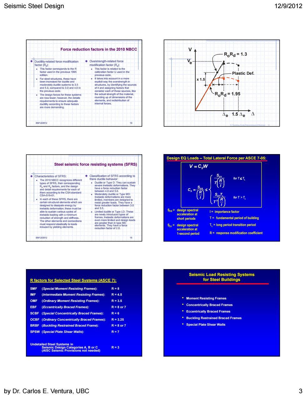
Seismic Steel Design 12/9/2012 ion factors in the 2010 RR=1.3 1.5△e Design EQ Loads-Total Lateral Force per ASCE7-05: V=CW (rA Tndanenpenodoiuen t年Tyha Tlong period transition perioc R=response modification coefficier R factors for Selected Stecl Systems (ASCE 7): trically Braced Frames): R-32 R= by Dr.Carlos E.Ventura,UBC 3 Seismic Steel Design 12/9/2012 by Dr. Carlos E. Ventura, UBC 3 09/12/2012 13 Overstrength-related force modification factor (Ro): This factor is related to the calibration factor U used in the previous code. It takes into account in a more explicit way the overstrength in structures, by identifying the sources of it and assigning factors that consider each of these sources, like the actual strength of the material, rounding up of dimensions of the elements, and redistribution of internal forces. Ductility-related force modification factor (Rd): This factor corresponds to the R factor used in the previous 1995 edition. For steel structures, these have been increased for ductile and moderately ductile systems to 3.5 and 5.0, compared to 3.0 and 4.0 in the previous code. The design forces for these systems are now lower; however, the details requirements to ensure adequate ductility according to these factors are more demanding. Force reduction factors in the 2010 NBCC V V 1.5 R R = 1.3 Plastic Def. e e e o d R R = 1.95 x 1.5 o d R. Tremblay, Ecole Polytechnique of Montreal 14 09/12/2012 15 Steel seismic force resisting systems (SFRS) Classification of SFRS according to there ductile behavior: Ductile or Type D: They can sustain severe inelastic deformations. They have a force reduction factor between 4.0 and 5.0. Moderately ductile or Type MD: Inelastic deformations are more limited, members are designed to resist greater loads. They have a force reduction factor between 3.0 and 3.5. Limited ductile or Type LD: These are newly introduced types of frames. Inelastic deformations are even more limited and design loads are greater than in type MD elements. They have a force reduction factor of 2.0. Characteristics of SFRS: The 2010 NBCC recognizes different types of SFRS, their corresponding Rd and Ro factors, and the design and detail requirements for each of them according to the CSA standard CSA-S16-01. In each of these SFRS, there are certain structural elements which are designed to dissipate energy by inelastic deformation; these must be able to sustain various cycles of inelastic loading with a minimum reduction of strength and stiffness. The other elements and connections must respond elastically to loads induced by yielding elements. Design EQ Loads – Total Lateral Force per ASCE 7-05: SDS = design spectral acceleration at short periods SD1 = design spectral acceleration at 1-second period I = importance factor R = response modification coefficient T = fundamental period of building V CSW I R S C DS S I R T SD1 I R T S T 2 D1 L for T TL for T > TL TL = long period transition period R factors for Selected Steel Systems (ASCE 7): SMF (Special Moment Resisting Frames): R = 8 IMF (Intermediate Moment Resisting Frames): R = 4.5 OMF (Ordinary Moment Resisting Frames): R = 3.5 EBF (Eccentrically Braced Frames): R = 8 or 7 SCBF (Special Concentrically Braced Frames): R = 6 OCBF (Ordinary Concentrically Braced Frames): R = 3.25 BRBF (Buckling Restrained Braced Frame): R = 8 or 7 SPSW (Special Plate Shear Walls): R = 7 Undetailed Steel Systems in Seismic Design Categories A, B or C R = 3 (AISC Seismic Provisions not needed) Seismic Load Resisting Systems for Steel Buildings • Moment Resisting Frames • Concentrically Braced Frames • Eccentrically Braced Frames • Buckling Restrained Braced Frames • Special Plate Shear Walls