正在加载图片...

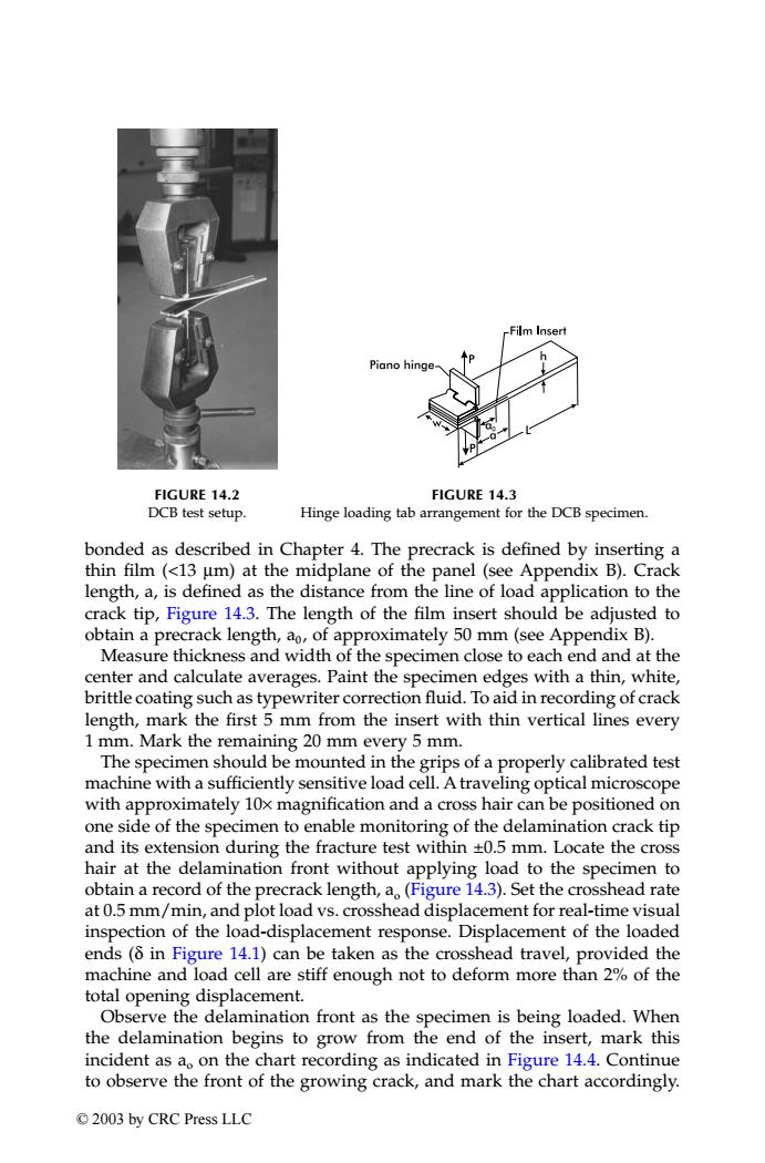
-Film Insert Piano hinge FIGURE 14.2 FIGURE 14.3 DCB test setup. Hinge loading tab arrangement for the DCB specimen. bonded as described in Chapter 4.The precrack is defined by inserting a thin film (<13 um)at the midplane of the panel(see Appendix B).Crack length,a,is defined as the distance from the line of load application to the crack tip,Figure 14.3.The length of the film insert should be adjusted to obtain a precrack length,ao,of approximately 50 mm(see Appendix B). Measure thickness and width of the specimen close to each end and at the center and calculate averages.Paint the specimen edges with a thin,white, brittle coating such as typewriter correction fluid.To aid in recording of crack length,mark the first 5 mm from the insert with thin vertical lines every 1 mm.Mark the remaining 20 mm every 5 mm. The specimen should be mounted in the grips of a properly calibrated test machine with a sufficiently sensitive load cell.A traveling optical microscope with approximately 10x magnification and a cross hair can be positioned on one side of the specimen to enable monitoring of the delamination crack tip and its extension during the fracture test within +0.5 mm.Locate the cross hair at the delamination front without applying load to the specimen to obtain a record of the precrack length,a(Figure 14.3).Set the crosshead rate at 0.5 mm/min,and plot load vs.crosshead displacement for real-time visual inspection of the load-displacement response.Displacement of the loaded ends(8 in Figure 14.1)can be taken as the crosshead travel,provided the machine and load cell are stiff enough not to deform more than 2%of the total opening displacement. Observe the delamination front as the specimen is being loaded.When the delamination begins to grow from the end of the insert,mark this incident as ao on the chart recording as indicated in Figure 14.4.Continue to observe the front of the growing crack,and mark the chart accordingly. ©2003 by CRC Press LLCbonded as described in Chapter 4. The precrack is defined by inserting a thin film (<13 µm) at the midplane of the panel (see Appendix B). Crack length, a, is defined as the distance from the line of load application to the crack tip, Figure 14.3. The length of the film insert should be adjusted to obtain a precrack length, a0 , of approximately 50 mm (see Appendix B). Measure thickness and width of the specimen close to each end and at the center and calculate averages. Paint the specimen edges with a thin, white, brittle coating such as typewriter correction fluid. To aid in recording of crack length, mark the first 5 mm from the insert with thin vertical lines every 1 mm. Mark the remaining 20 mm every 5 mm. The specimen should be mounted in the grips of a properly calibrated test machine with a sufficiently sensitive load cell. A traveling optical microscope with approximately 10× magnification and a cross hair can be positioned on one side of the specimen to enable monitoring of the delamination crack tip and its extension during the fracture test within ±0.5 mm. Locate the cross hair at the delamination front without applying load to the specimen to obtain a record of the precrack length, ao (Figure 14.3). Set the crosshead rate at 0.5 mm/min, and plot load vs. crosshead displacement for real-time visual inspection of the load-displacement response. Displacement of the loaded ends (δ in Figure 14.1) can be taken as the crosshead travel, provided the machine and load cell are stiff enough not to deform more than 2% of the total opening displacement. Observe the delamination front as the specimen is being loaded. When the delamination begins to grow from the end of the insert, mark this incident as ao on the chart recording as indicated in Figure 14.4. Continue to observe the front of the growing crack, and mark the chart accordingly. FIGURE 14.2 DCB test setup. FIGURE 14.3 Hinge loading tab arrangement for the DCB specimen. TX001_ch14_Frame Page 188 Saturday, September 21, 2002 5:09 AM © 2003 by CRC Press LLC