正在加载图片...
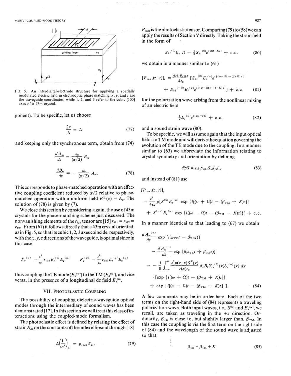
YARIV:COUPLED-MODE THEORY 927 P isthephotoelastictensor.Comparing(79)to(58)wecan apply the results of Section V directly.Taking the strain field in the form of guiding layer Sk:@G,)=&S四eo-Ka》十c.c. (80) we obtain in a manner similar to (61) 【PorG,tl,=D迪【S,@Eeew+8t-a+ 4e0 Fig.5.An interdigital-electrode structure for applying a spatially S(-E(eto-mt-(8-k)]c.c. (81) modulated electric field in electrooptic phase matching.x,y,and z are the waveguide coordinates,while 1,2,and 3 refer to the cubic [100] for the polarization wave arising from the nonlinear mixing axes of a 43m crystal. of an electric field ponent).To be specific,let us choose eftut-8)+c.c. (82) 2领=△ (77) and a sound strain wave (80). A To be specific,we will assume again that the input optical field is a TM mode and will derivetheequation governingthe and keeping only the synchronous term,obtain from(74) evolution of the TE mode due to the coupling.In a manner dA地= similar to(63)we abbreviate the information relating to crystal symmetry and orientation by defining -为4 epS=PSliy (83) (78) dz and instead of(81)use This corresponds to phase-matched operation with an effec- tive coupling coefficient reduced by a/2 relative to phase- [Per红,tle matched operation with a uniform field Et(z)=Eo.The solution of(78)is given by (7). 年6psE,ep{e+r-Bru+0 We close this section by considering,again,the use of 43m crystals for the phase-matching scheme just discussed.The +S(-E()exp (il(@-2)t -(Brxt -K)z]]+c.c. nonvanishing elements of the rux tensor are [15]raa rai2= In a manner identical to that leading to (67)we obtain r12.From(61)it follows directly that a 43m crystal oriented, as in Fig.5,so that its cubic 1,2,3axes coincide,respectively, dA (+ with thex,y,zdirections ofthe waveguide,is optimal sincein da exp[i(rEt-8re2刃 this case 、d4f) deexp (i(ret+Bz)] P,w=兰nnE,oE,e P,oi=至naE,oE, -看9aa定,"eg E(x)Eo thus coupling the TE mode(E,()to the TM(Ex(4),and vice versa,in the presence of a longitudinal dc field E,(0. .[exp (i[(+2)t -(8TM+K)z] expi(@-2)t -(BTM -K)z]]] (84) VII.PHOTOELASTIC COUPLING The possibility of coupling dielectric-waveguide optical A few comments may be in order here.Each of the two modes through the intermediary of sound waves has been terms on the right-hand side of(84)represents a traveling demonstrated [17].In this section we will treat this class ofin- polarization wave.Both input waves,i.e.,S and E(,we teractions using the coupled-mode formalism. recall,are taken as traveling in the +z direction.Or- The photoelastic effect is defined by relating the effect of dinarily,BrE is close to,but slightly larger than,BrM.In this case the coupling is via the first term on the right side strain Sw on the constants of the index ellipsoid through [18] of(84)and the wavelength of the sound wave is adjusted so that =Piik SL. (79) BTE =BTM+K (85)YARIV: COUPLED-MODE THEORY 927 Pijklisthephotoelastictensor.Comparing(79)to(58)wecan apply the results of Section V directly. Taking the strain field in the form of w guiding layer we obtain in a manner similar to (61) Fig. 5. An interdigital-electrode structure for applying aspatially modulated electric field in electrooptic phase matching. x, y, and z are the waveguide coordinates, while 1, 2, and 3 refer to the cubic [IOO] axes of a $3171 crystal. ponent). To be specific, let us choose (77) and keeping only the synchronous term, obtain from (74) This corresponds to phase-matched operation with an effective coupling coefficient reduced by ~/2 relative to phasematched operation with a uniform field E(O)(z) = Eo. The solution of (78) is given by (7). We close this section by considering, again, the use of43m crystals for the phase-matching scheme just discussed. The nonvanishing elements of the iijk tensor are [ 151 raZ1 = rslz = r123. From (61) it follows directly that a43m crystal oriented, as in Fig. 5, so that its cubic 1,2,3 axescoincide, respectively, with thex,y,zdirectionsofthewaveguide,isoptimalsincein this case thus coupling theTE mode(E,'"') to theTM (Ex(")), andvice versa, in the presence of a longitudinal dc field E,('). for the polarization wave arising from the nonlinear mixing of an electric field and a sound strain wave (80). To be specific, we will assume again that the input optical field is a TM mode and will derive the equation governing the evolution of the TE mode due to the coupling. In a manner similar to (63) we abbreviate the information relating to crystal symmetry and orientation by defining and instead of (81) use VII. PHOTOELASTIC COUPLING A few comments may be in order here. Each of the two The possibility Of dielectric-waveguide Optical terms on the right-hand side of (84) represents a traveling modes through the intermediary Of sound has been polarization wave. Both input waves, i.e., S(0) and Ex(@), we demonstrated [ 171. In thissectionwewill treat thisclassofin- recall, are taken as traveling in the +z direction. Orteractions using the coupled-mode formalism. dinarily, PTE is close to, but slightly larger than, PTM. In The photoelastic effect is defined by relating the effect of this the coupling is via the first term on the right side on theconstants oftheindexellipsoid through [I81 of (84) and the wavelength of the sound wave is adjusted so that (79) PTE = PTM + K