正在加载图片...
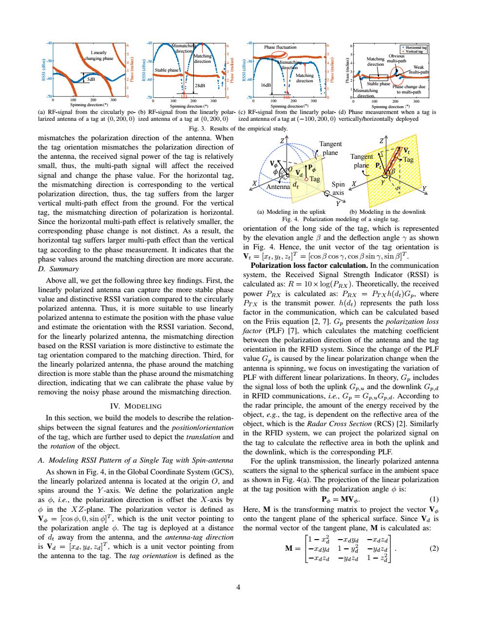
Phase fluctuation Weak Stable pha muti-pat业 Stable pha to mull山-pah direction. 00 00 100 200 300 100 200 0 100 200 300 Spinning direction() Spinning direction() Spinming direction() pinning (a)RF-signal from the circularly po-(b)RF-signal from the linearly polar-(c)RF-signal from the linearly polar-(d)Phase measurement when a tag is larized antenna of a tag at (0,200,0)ized antenna of a tag at (0,200,0)ized antenna of a tag at(-100,200.0)vertically/horizontally deployed Fig.3.Results of the empirical study mismatches the polarization direction of the antenna.When the tag orientation mismatches the polarization direction of Tangent the antenna,the received signal power of the tag is relatively plane Tangent small,thus,the multi-path signal will affect the received plane signal and change the phase value.For the horizontal tag, the mismatching direction is corresponding to the vertical Antenna Spin polarization direction,thus,the tag suffers from the larger axis vertical multi-path effect from the ground.For the vertical ps tag,the mismatching direction of polarization is horizontal. (a)Modeling in the uplink (b)Modeling in the downlink Since the horizontal multi-path effect is relatively smaller,the Fig.4.Polarization modeling of a single tag. corresponding phase change is not distinct.As a result,the orientation of the long side of the tag,which is represented horizontal tag suffers larger multi-path effect than the vertical by the elevation angle B and the deflection angle yy as shown tag according to the phase measurement.It indicates that the in Fig.4.Hence,the unit vector of the tag orientation is phase values around the matching direction are more accurate. V:=[t,Ut=[cos B cos7,cos Bsin y,sin BT. D.Summary Polarization loss factor calculation.In the communication system.the Received Signal Strength Indicator (RSSI)is Above all,we get the following three key findings.First,the calculated as:R=10x log(PRx).Theoretically,the received linearly polarized antenna can capture the more stable phase power PRx is calculated as:PRx Prxh(dt)Gp,where value and distinctive RSSI variation compared to the circularly polarized antenna.Thus,it is more suitable to use linearly Prx is the transmit power.h(dt)represents the path loss factor in the communication,which can be calculated based polarized antenna to estimate the position with the phase value on the Friis equation [2,7].Gp presents the polarization loss and estimate the orientation with the RSSI variation.Second. factor (PLF)[7],which calculates the matching coefficient for the linearly polarized antenna,the mismatching direction between the polarization direction of the antenna and the tag based on the RSSI variation is more distinctive to estimate the orientation in the RFID system.Since the change of the PLF tag orientation compared to the matching direction.Third,for value Gp is caused by the linear polarization change when the the linearly polarized antenna,the phase around the matching antenna is spinning,we focus on investigating the variation of direction is more stable than the phase around the mismatching PLF with different linear polarizations.In theory,G includes direction,indicating that we can calibrate the phase value by the signal loss of both the uplink Gp.u and the downlink Gp.d removing the noisy phase around the mismatching direction. in RFID communications,i.e.,Gp Gp.uGp,d.According to IV.MODELING the radar principle,the amount of the energy received by the In this section,we build the models to describe the relation- object,e.g.,the tag,is dependent on the reflective area of the ships between the signal features and the position/orientation object,which is the Radar Cross Section(RCS)[2].Similarly of the tag,which are further used to depict the translation and in the RFID system,we can project the polarized signal on the rotation of the object. the tag to calculate the reflective area in both the uplink and the downlink,which is the corresponding PLF. A.Modeling RSSI Pattern of a Single Tag with Spin-antenna For the uplink transmission,the linearly polarized antenna As shown in Fig.4,in the Global Coordinate System(GCS). scatters the signal to the spherical surface in the ambient space the linearly polarized antenna is located at the origin O,and as shown in Fig.4(a).The projection of the linear polarization spins around the Y-axis.We define the polarization angle at the tag position with the polarization angle is: as o,i.e.,the polarization direction is offset the X-axis by P。=MVo (1) in the XZ-plane.The polarization vector is defined as Here,M is the transforming matrix to project the vector Vo V=[cos,0,sin,which is the unit vector pointing to onto the tangent plane of the spherical surface.Since Va is the polarization angle The tag is deployed at a distance the normal vector of the tangent plane,M is calculated as: of dt away from the antenna,and the antenna-tag direction [1-x -Tdyd -Tdzd is Va =[rd,yd,zd]T,which is a unit vector pointing from M 1-yi -Yd2d (2) the antenna to the tag.The tag orientation is defined as the -Tdzd -Ydzd 1-20 100 200 300 Antenna direction (°) -70 -60 -50 -40 RSSI (dBm) 0 1 2 3 4 5 6 Phase (radian) 5dB Linearly changing phase Spinning direction (a) RF-signal from the circularly polarized antenna of a tag at (0, 200, 0) 0 100 200 300 Antenna direction (°) -70 -60 -50 -40 RSSI (dBm) 0 1 2 3 4 5 6 Phase (radian) Stable phase 28dB Matching direction Mismatching direction Spinning direction 153 (b) RF-signal from the linearly polarized antenna of a tag at (0, 200, 0) 0 100 200 300 Antenna direction (°) -70 -60 -50 -40 RSSI (dBm) 0 1 2 3 4 5 6 Phase (radian) Matching direction Mismatching direction 16dB Phase fluctuation Spinning direction 166 (c) RF-signal from the linearly polarized antenna of a tag at (−100, 200, 0) 0 100 200 300 Antenna direction (°) 0 1 2 3 4 5 6 Phase (radian) Horizontal tag Vertical tag Stable phase Phase change due to multi-path Weak multi-path Obvious multi-path Matching direction Mismatching direction Spinning direction (d) Phase measurement when a tag is vertically/horizontally deployed Fig. 3. Results of the empirical study. mismatches the polarization direction of the antenna. When the tag orientation mismatches the polarization direction of the antenna, the received signal power of the tag is relatively small, thus, the multi-path signal will affect the received signal and change the phase value. For the horizontal tag, the mismatching direction is corresponding to the vertical polarization direction, thus, the tag suffers from the larger vertical multi-path effect from the ground. For the vertical tag, the mismatching direction of polarization is horizontal. Since the horizontal multi-path effect is relatively smaller, the corresponding phase change is not distinct. As a result, the horizontal tag suffers larger multi-path effect than the vertical tag according to the phase measurement. It indicates that the phase values around the matching direction are more accurate. D. Summary Above all, we get the following three key findings. First, the linearly polarized antenna can capture the more stable phase value and distinctive RSSI variation compared to the circularly polarized antenna. Thus, it is more suitable to use linearly polarized antenna to estimate the position with the phase value and estimate the orientation with the RSSI variation. Second, for the linearly polarized antenna, the mismatching direction based on the RSSI variation is more distinctive to estimate the tag orientation compared to the matching direction. Third, for the linearly polarized antenna, the phase around the matching direction is more stable than the phase around the mismatching direction, indicating that we can calibrate the phase value by removing the noisy phase around the mismatching direction. IV. MODELING In this section, we build the models to describe the relationships between the signal features and the position/orientation of the tag, which are further used to depict the translation and the rotation of the object. A. Modeling RSSI Pattern of a Single Tag with Spin-antenna As shown in Fig. 4, in the Global Coordinate System (GCS), the linearly polarized antenna is located at the origin O, and spins around the Y -axis. We define the polarization angle as φ, i.e., the polarization direction is offset the X-axis by φ in the XZ-plane. The polarization vector is defined as Vφ = [cos φ, 0,sin φ] T , which is the unit vector pointing to the polarization angle φ. The tag is deployed at a distance of dt away from the antenna, and the antenna-tag direction is Vd = [xd, yd, zd] T , which is a unit vector pointing from the antenna to the tag. The tag orientation is defined as the � � � � � � �' Tangent plane �' Tag � � � �* Antenna Tangent plane Spin axis �* �+ � Tag �' (a) Modeling in the uplink � � � � � � �' Tangent plane �' Tag � � � �* Antenna Tangent plane Spin axis �* �+ � Tag �' (b) Modeling in the downlink Fig. 4. Polarization modeling of a single tag. orientation of the long side of the tag, which is represented by the elevation angle β and the deflection angle γ as shown in Fig. 4. Hence, the unit vector of the tag orientation is Vt = [xt, yt, zt] T = [cos β cos γ, cos β sin γ,sin β] T . Polarization loss factor calculation. In the communication system, the Received Signal Strength Indicator (RSSI) is calculated as: R = 10×log(PRX). Theoretically, the received power PRX is calculated as: PRX = PTXh(dt)Gp, where PTX is the transmit power. h(dt) represents the path loss factor in the communication, which can be calculated based on the Friis equation [2, 7]. Gp presents the polarization loss factor (PLF) [7], which calculates the matching coefficient between the polarization direction of the antenna and the tag orientation in the RFID system. Since the change of the PLF value Gp is caused by the linear polarization change when the antenna is spinning, we focus on investigating the variation of PLF with different linear polarizations. In theory, Gp includes the signal loss of both the uplink Gp,u and the downlink Gp,d in RFID communications, i.e., Gp = Gp,uGp,d. According to the radar principle, the amount of the energy received by the object, e.g., the tag, is dependent on the reflective area of the object, which is the Radar Cross Section (RCS) [2]. Similarly in the RFID system, we can project the polarized signal on the tag to calculate the reflective area in both the uplink and the downlink, which is the corresponding PLF. For the uplink transmission, the linearly polarized antenna scatters the signal to the spherical surface in the ambient space as shown in Fig. 4(a). The projection of the linear polarization at the tag position with the polarization angle φ is: Pφ = MVφ. (1) Here, M is the transforming matrix to project the vector Vφ onto the tangent plane of the spherical surface. Since Vd is the normal vector of the tangent plane, M is calculated as: M = 1 − x 2 d −xdyd −xdzd −xdyd 1 − y 2 d −ydzd −xdzd −ydzd 1 − z 2 d . (2) 4