正在加载图片...
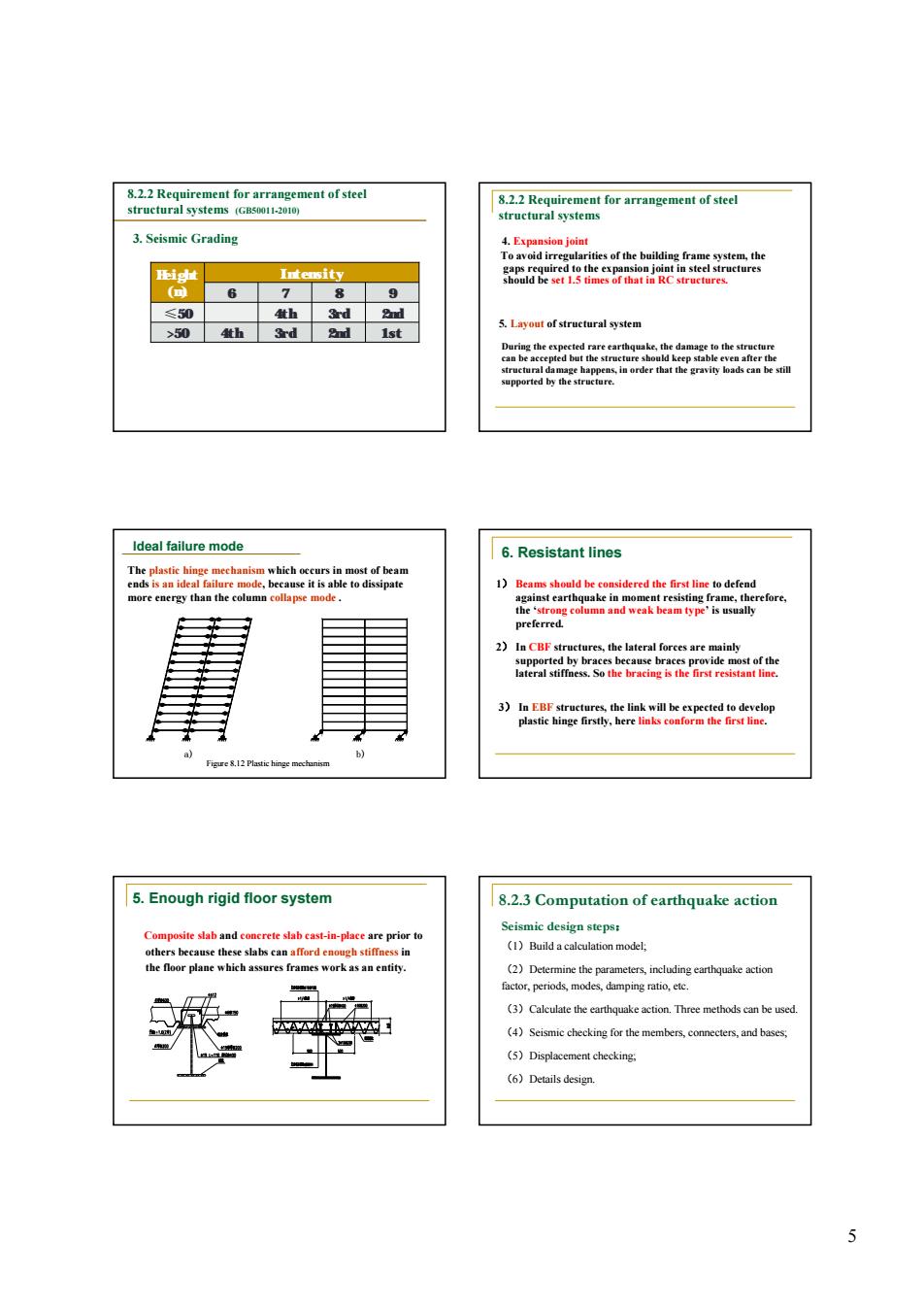
2agrmgmcaoa 3.Seismic Grading 袋 ≤50 4th 3rd 2nd 5.Laveut ef strustural svstem 504h 3d 2nd 1st ldeal failure mode 6.Resistant lines 2)In CBF st )hekaeteee 5.Enough rigid floor system 8.2.3 Computation of earthquake action e slab cast-in-pl 密 (3)Calculale the earthquake action.Three methods can be used (4)Seismic checkine for the members.comnecters.and bases. (5)Displacement checking (6)Details design5 3. Seismic Grading 8.2.2 Requirement for arrangement of steel structural systems (GB50011-2010) Height (m) Intensity 6 7 8 9 ≤50 4th 3rd 2nd >50 4th 3rd 2nd 1st 4. Expansion joint To avoid irregularities of the building frame system, the gaps required to the expansion joint in steel structures should be set 1.5 times of that in RC structures. 5. Layout of structural system During the expected rare earthquake, the damage to the structure can be accepted but the structure should keep stable even after the structural damage happens, in order that the gravity loads can be still supported by the structure. 8.2.2 Requirement for arrangement of steel structural systems a) b) The plastic hinge mechanism which occurs in most of beam ends is an ideal failure mode, because it is able to dissipate more energy than the column collapse mode . Figure 8.12 Plastic hinge mechanism Ideal failure mode 2) In CBF structures, the lateral forces are mainly supported by braces because braces provide most of the lateral stiffness. So the bracing is the first resistant line. 3) In EBF structures, the link will be expected to develop plastic hinge firstly, here links conform the first line. 1) Beams should be considered the first line to defend against earthquake in moment resisting frame, therefore, the ‘strong column and weak beam type’ is usually preferred. 6. Resistant lines 5. Enough rigid floor system Composite slab and concrete slab cast-in-place are prior to others because these slabs can afford enough stiffness in the floor plane which assures frames work as an entity. (1)Build a calculation model; (2)Determine the parameters, including earthquake action factor, periods, modes, damping ratio, etc. (3)Calculate the earthquake action. Three methods can be used. (4)Seismic checking for the members, connecters, and bases; (5)Displacement checking; (6)Details design. 8.2.3 Computation of earthquake action Seismic design steps: