正在加载图片...

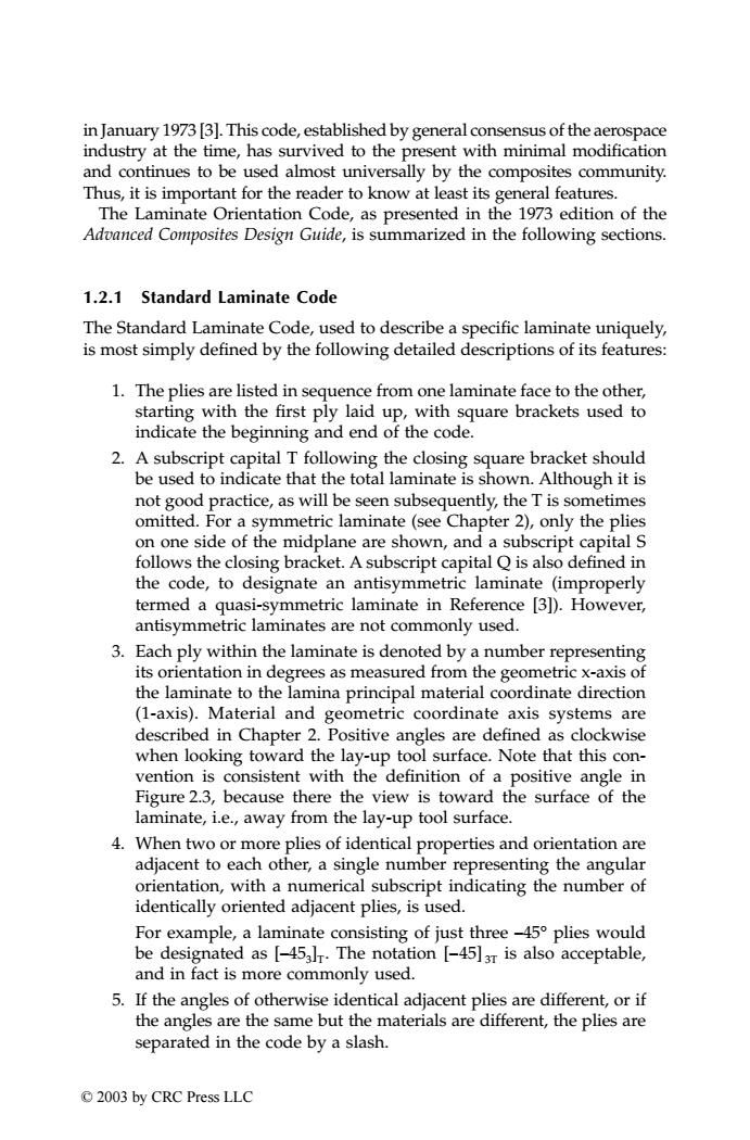
in January 1973 [3].This code,established by general consensus of the aerospace industry at the time,has survived to the present with minimal modification and continues to be used almost universally by the composites community. Thus,it is important for the reader to know at least its general features. The Laminate Orientation Code,as presented in the 1973 edition of the Advanced Composites Design Guide,is summarized in the following sections. 1.2.1 Standard Laminate Code The Standard Laminate Code,used to describe a specific laminate uniquely, is most simply defined by the following detailed descriptions of its features: 1.The plies are listed in sequence from one laminate face to the other, starting with the first ply laid up,with square brackets used to indicate the beginning and end of the code. 2.A subscript capital T following the closing square bracket should be used to indicate that the total laminate is shown.Although it is not good practice,as will be seen subsequently,the T is sometimes omitted.For a symmetric laminate(see Chapter 2),only the plies on one side of the midplane are shown,and a subscript capital S follows the closing bracket.A subscript capital Q is also defined in the code,to designate an antisymmetric laminate (improperly termed a quasi-symmetric laminate in Reference [3]).However, antisymmetric laminates are not commonly used. 3.Each ply within the laminate is denoted by a number representing its orientation in degrees as measured from the geometric x-axis of the laminate to the lamina principal material coordinate direction (1-axis).Material and geometric coordinate axis systems are described in Chapter 2.Positive angles are defined as clockwise when looking toward the lay-up tool surface.Note that this con- vention is consistent with the definition of a positive angle in Figure 2.3,because there the view is toward the surface of the laminate,i.e.,away from the lay-up tool surface. 4.When two or more plies of identical properties and orientation are adjacent to each other,a single number representing the angular orientation,with a numerical subscript indicating the number of identically oriented adjacent plies,is used. For example,a laminate consisting of just three-45 plies would be designated as [-45al.The notation [-45]3r is also acceptable, and in fact is more commonly used. 5.If the angles of otherwise identical adjacent plies are different,or if the angles are the same but the materials are different,the plies are separated in the code by a slash. ©2003 by CRC Press LLCin January 1973 [3]. This code, established by general consensus of the aerospace industry at the time, has survived to the present with minimal modification and continues to be used almost universally by the composites community. Thus, it is important for the reader to know at least its general features. The Laminate Orientation Code, as presented in the 1973 edition of the Advanced Composites Design Guide, is summarized in the following sections. 1.2.1 Standard Laminate Code The Standard Laminate Code, used to describe a specific laminate uniquely, is most simply defined by the following detailed descriptions of its features: 1. The plies are listed in sequence from one laminate face to the other, starting with the first ply laid up, with square brackets used to indicate the beginning and end of the code. 2. A subscript capital T following the closing square bracket should be used to indicate that the total laminate is shown. Although it is not good practice, as will be seen subsequently, the T is sometimes omitted. For a symmetric laminate (see Chapter 2), only the plies on one side of the midplane are shown, and a subscript capital S follows the closing bracket. A subscript capital Q is also defined in the code, to designate an antisymmetric laminate (improperly termed a quasi-symmetric laminate in Reference [3]). However, antisymmetric laminates are not commonly used. 3. Each ply within the laminate is denoted by a number representing its orientation in degrees as measured from the geometric x-axis of the laminate to the lamina principal material coordinate direction (1-axis). Material and geometric coordinate axis systems are described in Chapter 2. Positive angles are defined as clockwise when looking toward the lay-up tool surface. Note that this convention is consistent with the definition of a positive angle in Figure 2.3, because there the view is toward the surface of the laminate, i.e., away from the lay-up tool surface. 4. When two or more plies of identical properties and orientation are adjacent to each other, a single number representing the angular orientation, with a numerical subscript indicating the number of identically oriented adjacent plies, is used. For example, a laminate consisting of just three –45° plies would be designated as [–453]T. The notation [–45] 3T is also acceptable, and in fact is more commonly used. 5. If the angles of otherwise identical adjacent plies are different, or if the angles are the same but the materials are different, the plies are separated in the code by a slash. TX001_ch01_Frame Page 4 Saturday, September 21, 2002 4:47 AM © 2003 by CRC Press LLC