正在加载图片...
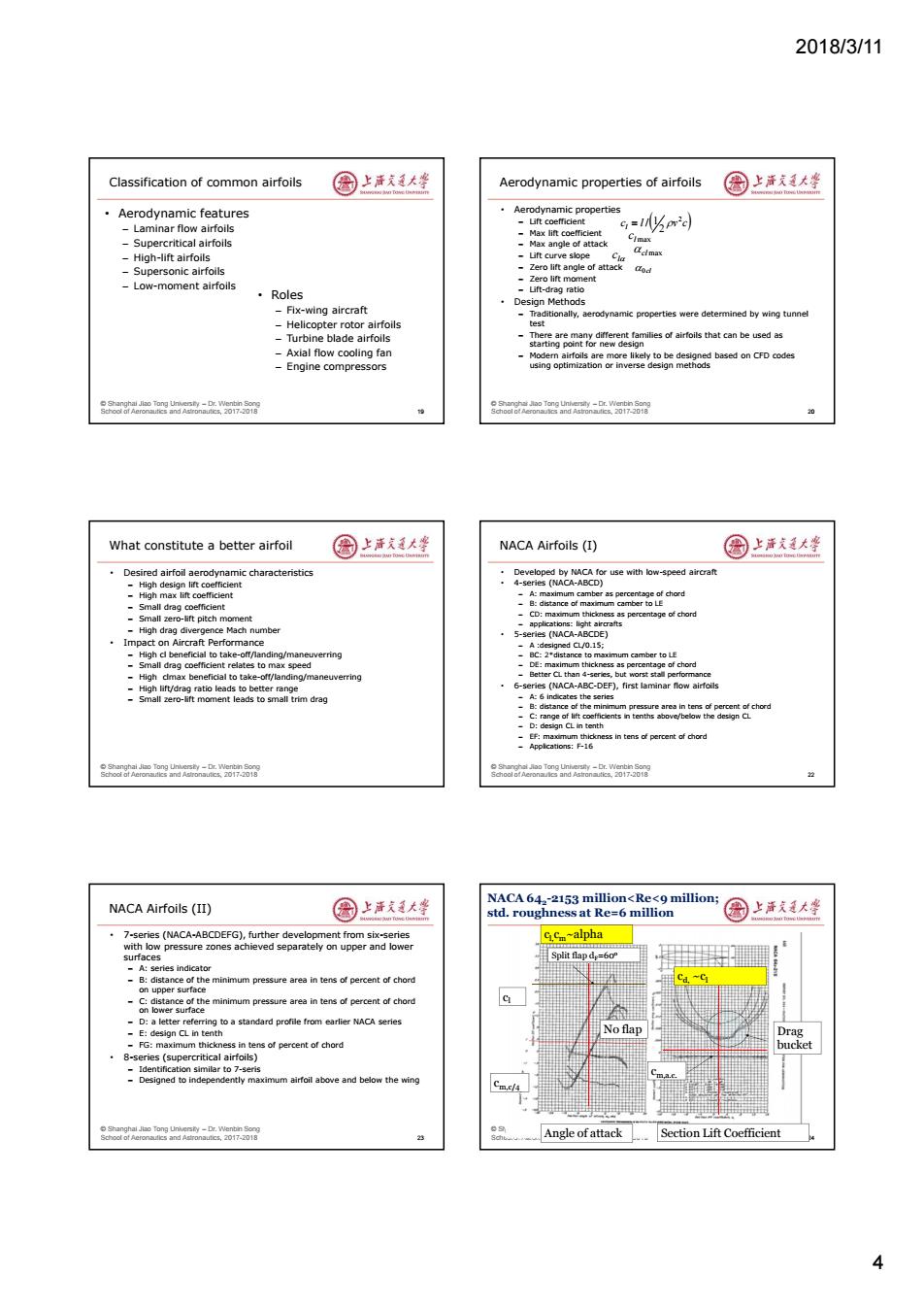
2018/3/11 Classification of common airfoils 国上唐美大坐 Aerodynamic properties of airfoils 国上清大学 Aerodynamic features Aerodynamic properties -Laminar flow airfoils =15pm2d -Supercritical airfolls Clmax -High-lift airfoils -Lift curve slope Cla Celmax -Supersonic airfoils -Zero lift angle of attack od -Zero lift moment -Low-moment airfoils ·Roles Lift-drag ratio ·Design Methods Fix-wing aircraft -Traditionally,aerodynamic properties were determined by wing tunnel -Helicopter rotor airfoils test -Turbine blade airfoils -There are ma starting point for new design ent families of airfoils that can be used as Axial flow cooling fan Modern airfoils are more likely to be designed based on CFD codes Engine compressors using optimization or inverse design methods r nd 7 What constitute a better airfoil 国上活美大坐 NACA Airfoils(I) 圆上洋发廷大坐 Desired airfoil aerodynamic characteristics Developed by NACAfor use with low-speed aircrat -High design lift coefficient 4-series (NACA-ABCD) -High max lift coefficient -Small drag coefficient -Small zerc -tift oitch moment -High drag divergence Mach number 5-series (NACA-ABCDE) Impact on Aircraft Performance A :designed CL/0.1S; -High dl beneficial to take-off/landing/maneuverring BC:2*distance to maximum camber toLE -Small drag coefficient relates to max speed -High cmax beneficial to take-off/landing/maneuverring nce -High lift/drag ratio leads to better range 6-series (NACA-ABC-DEF),first laminar flow airfoils -Small zero-lift moment leads to small trim drag the series eesnod D:design CL in tenth EF:maximum thickness in tens of percent of chord eagaea2-w58 NACA Airfoils(II) 国上洋大坐 NACA 642-2153 million<Re<9 million; std.roughness at Re=6 million 园上声戈是大学 7-series (NACA-ABCDEFG).further develo nent from six-series pressure zones achieved separately on upper and lower C.Cm~alpha Split flap d=60P ries indicator -B:distance o the minimum pressure area in tens of percent of chord ca ~C pper minimum pressure area in tens of percent of chord -D:a letter referring to a standard profile from earlier NACA series -E:design CL in nth Noflap Drag FG:maximum thi ess in tens of percent of chord bucket 8-series (supercritical airfoils) -Identification similar to 7-seris -Designed to independently maximum airfoil above and below the wing Cm.c/ 23 Angle ofattack Section Lift Coefficient 42018/3/11 4 © Shanghai Jiao Tong University – Dr. Wenbin Song School of Aeronautics and Astronautics, 2017-2018 Classification of common airfoils • Aerodynamic features – Laminar flow airfoils – Supercritical airfoils – High-lift airfoils – Supersonic airfoils – Low-moment airfoils 19 • Roles – Fix-wing aircraft – Helicopter rotor airfoils – Turbine blade airfoils – Axial flow cooling fan – Engine compressors © Shanghai Jiao Tong University – Dr. Wenbin Song School of Aeronautics and Astronautics, 2017-2018 Aerodynamic properties of airfoils • Aerodynamic properties – Lift coefficient – Max lift coefficient – Max angle of attack – Lift curve slope – Zero lift angle of attack – Zero lift moment – Lift-drag ratio • Design Methods – Traditionally, aerodynamic properties were determined by wing tunnel test – There are many different families of airfoils that can be used as starting point for new design – Modern airfoils are more likely to be designed based on CFD codes using optimization or inverse design methods 20 c l v c l 2 2 / 1 l max c l c cl max 0cl © Shanghai Jiao Tong University – Dr. Wenbin Song School of Aeronautics and Astronautics, 2017-2018 What constitute a better airfoil • Desired airfoil aerodynamic characteristics – High design lift coefficient – High max lift coefficient – Small drag coefficient – Small zero-lift pitch moment – High drag divergence Mach number • Impact on Aircraft Performance – High cl beneficial to take-off/landing/maneuverring – Small drag coefficient relates to max speed – High clmax beneficial to take-off/landing/maneuverring – High lift/drag ratio leads to better range – Small zero-lift moment leads to small trim drag © Shanghai Jiao Tong University – Dr. Wenbin Song School of Aeronautics and Astronautics, 2017-2018 NACA Airfoils (I) • Developed by NACA for use with low-speed aircraft • 4-series (NACA-ABCD) – A: maximum camber as percentage of chord – B: distance of maximum camber to LE – CD: maximum thickness as percentage of chord – applications: light aircrafts • 5-series (NACA-ABCDE) – A :designed CL/0.15; – BC: 2*distance to maximum camber to LE – DE: maximum thickness as percentage of chord – Better CL than 4-series, but worst stall performance • 6-series (NACA-ABC-DEF), first laminar flow airfoils – A: 6 indicates the series – B: distance of the minimum pressure area in tens of percent of chord – C: range of lift coefficients in tenths above/below the design CL – D: design CL in tenth – EF: maximum thickness in tens of percent of chord – Applications: F-16 22 © Shanghai Jiao Tong University – Dr. Wenbin Song School of Aeronautics and Astronautics, 2017-2018 NACA Airfoils (II) • 7-series (NACA-ABCDEFG), further development from six-series with low pressure zones achieved separately on upper and lower surfaces – A: series indicator – B: distance of the minimum pressure area in tens of percent of chord on upper surface – C: distance of the minimum pressure area in tens of percent of chord on lower surface – D: a letter referring to a standard profile from earlier NACA series – E: design CL in tenth – FG: maximum thickness in tens of percent of chord • 8-series (supercritical airfoils) – Identification similar to 7-seris – Designed to independently maximum airfoil above and below the wing 23 © Shanghai Jiao Tong University – Dr. Wenbin Song School of Aeronautics and Astronautics, 2017-2018 24 Split flap dF=60o No flap cl cm,c/4 Drag bucket cm,a.c. Angle of attack Section Lift Coefficient NACA 642 -2153 million<Re<9 million; std. roughness at Re=6 million cl,cm~alpha cd, ~cl