正在加载图片...

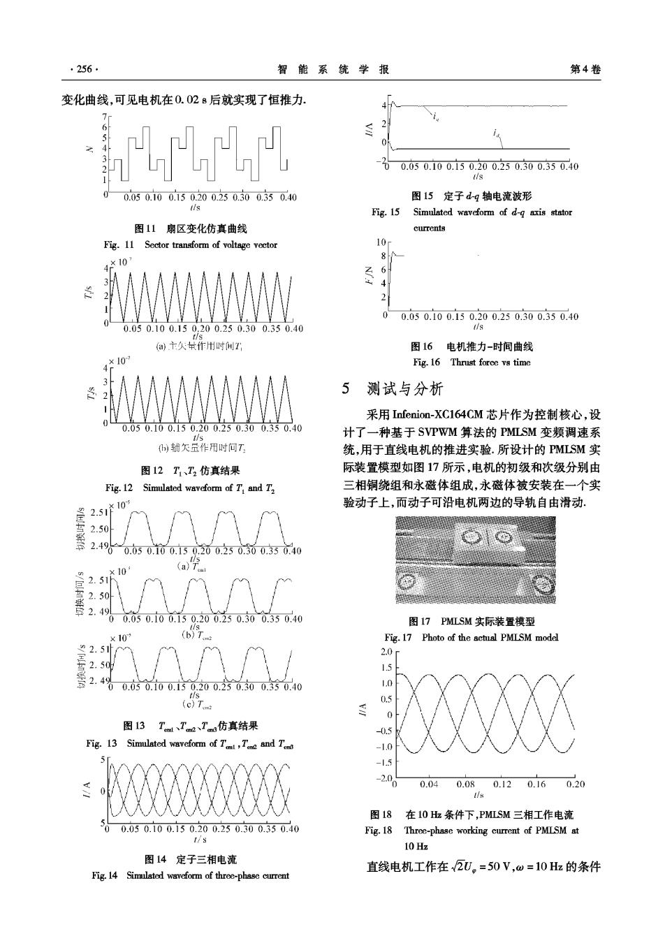
·256 智能系统学报 第4卷 变化曲线,可见电机在0.028后就实现了恒推力. H 00.050.100.150.200.250.300.350.40 lis 0.050.100.150.200.250.300.350.40 图15定子d-g轴电流波形 Ws Fig.15 Simulated waveform of d-g axis stator 图11扇区变化仿真曲线 currents Fig.11 Sector transform of voltage vector 10 8 410 2 0 0.050.100.150.200.250.300.350.40 0.050.100.150.200.250.300.350.40 dls @主久式作州时州T 图16电机推力-时间曲线 ×107 Fig.16 Thrust force vs time 3 5 测试与分析 采用Infenion-XC164CM芯片作为控制核心,设 0.050.100.150.200.250.300.350.40 计了一种基于SVPWM算法的PMLSM变频调速系 b)甜欠金作用时何T 统,用于直线电机的推进实验.所设计的PMLSM实 图12T1、T2仿真结果 际装置模型如图17所示,电机的初级和次级分别由 Fig.12 Simulated waveform of T and T 三相铜绕组和永磁体组成,永磁体被安装在一个实 2.51产10 验动子上,而动子可沿电机两边的导轨自由滑动. 2.50 毫2.4960.050.100.50.200.250.300.350.40 10 (a) 2.51h 2.50 00.050.100.150.200.250.300.35040 图17 PMLSM实际装置模型 ×10 (b)Tam Fig.17 Photo of the actual PMISM model 2.5 20 2.50 1.5 4 00.050.100.150.200.250.300.350.40 1.0 (cT.m 0.5 ≤ 0 图13Tml、了2、Tm仿真结果 -0.5 Fig.13 Simulated waveform of T,T and T -1.0 5 -1.5 2.00 0.040.080.120.160.20 图18在10H条件下,PMLSM三相工作电流 0.050.100.150.200.250.300.350.40 Fig.18 Three-phase working current of PMLSM at 1/s 10 Hz 图14定子三相电流 直线电机工作在2U。=50V,w=10Hz的条件 Fig.14 Simulated waveform of three-phase current