正在加载图片...
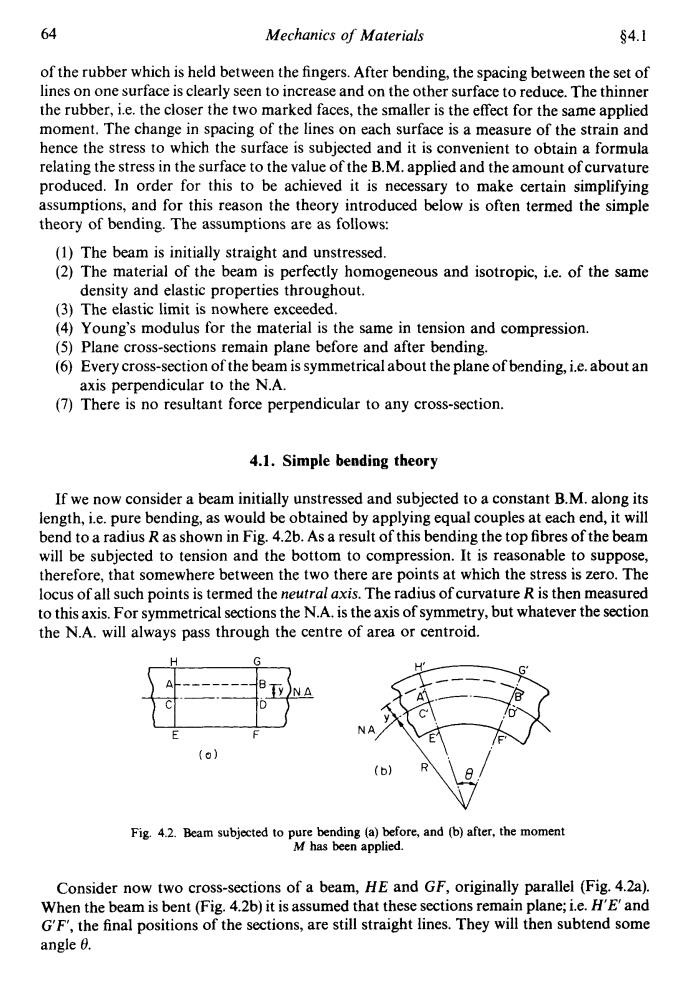
64 Mechanics of Materials §4.1 of the rubber which is held between the fingers.After bending,the spacing between the set of lines on one surface is clearly seen to increase and on the other surface to reduce.The thinner the rubber,i.e.the closer the two marked faces,the smaller is the effect for the same applied moment.The change in spacing of the lines on each surface is a measure of the strain and hence the stress to which the surface is subjected and it is convenient to obtain a formula relating the stress in the surface to the value of the B.M.applied and the amount of curvature produced.In order for this to be achieved it is necessary to make certain simplifying assumptions,and for this reason the theory introduced below is often termed the simple theory of bending.The assumptions are as follows: (1)The beam is initially straight and unstressed. (2)The material of the beam is perfectly homogeneous and isotropic,i.e.of the same density and elastic properties throughout. (3)The elastic limit is nowhere exceeded. (4)Young's modulus for the material is the same in tension and compression. (5)Plane cross-sections remain plane before and after bending. (6)Every cross-section of the beam is symmetrical about the plane of bending,i.e.about an axis perpendicular to the N.A. (7)There is no resultant force perpendicular to any cross-section. 4.1.Simple bending theory If we now consider a beam initially unstressed and subjected to a constant B.M.along its length,i.e.pure bending,as would be obtained by applying equal couples at each end,it will bend to a radius R as shown in Fig.4.2b.As a result of this bending the top fibres of the beam will be subjected to tension and the bottom to compression.It is reasonable to suppose, therefore,that somewhere between the two there are points at which the stress is zero.The locus of all such points is termed the neutral axis.The radius of curvature R is then measured to this axis.For symmetrical sections the N.A.is the axis of symmetry,but whatever the section the N.A.will always pass through the centre of area or centroid. (0】 (b) Fig.4.2.Beam subjected to pure bending (a)before,and (b)after,the moment M has been applied. Consider now two cross-sections of a beam,HE and GF,originally parallel (Fig.4.2a). When the beam is bent (Fig.4.2b)it is assumed that these sections remain plane;i.e.H'E'and G'F',the final positions of the sections,are still straight lines.They will then subtend some angle 0.64 Mechanics of Materials $4. I of the rubber which is held between the fingers. After bending, the spacing between the set of lines on one surface is clearly seen to increase and on the other surface to reduce. The thinner the rubber, i.e. the closer the two marked faces, the smaller is the effect for the same applied moment. The change in spacing of the lines on each surface is a measure of the strain and hence the stress to which the surface is subjected and it is convenient to obtain a formula relating the stress in the surface to the value of the B.M. applied and the amount of curvature produced. In order for this to be achieved it is necessary to make certain simplifying assumptions, and for this reason the theory introduced below is often termed the simple theory of bending. The assumptions are as follows: (1) The beam is initially straight and unstressed. (2) The material of the beam is perfectly homogeneous and isotropic, i.e. of the same density and elastic properties throughout. (3) The elastic limit is nowhere exceeded. (4) Young's modulus for the material is the same in tension and compression. (5) Plane cross-sections remain plane before and after bending. (6) Every cross-section of the beam is symmetrical about the plane of bending, i.e. about an (7) There is no resultant force perpendicular to any cross-section. axis perpendicular to the N.A. 4.1. Simple bending theory If we now consider a beam initially unstressed and subjected to a constant B.M. along its length, i.e. pure bending, as would be obtained by applying equal couples at each end, it will bend to a radius R as shown in Fig. 4.2b. As a result of this bending the top fibres of the beam will be subjected to tension and the bottom to compression. It is reasonable to suppose, therefore, that somewhere between the two there are points at which the stress is zero. The locus of all such points is termed the neutral axis. The radius of curvature R is then measured to this axis. For symmetrical sections the N.A. is the axis of symmetry, but whatever the section the N.A. will always pass through the centre of area or centroid. Fig. 4.2. Beam subjected to pure bending (a) before, and (b) after, the moment M has been applied. Consider now two cross-sections of a beam, HE and GF, originally parallel (Fig. 423). When the beam is bent (Fig. 4.2b) it is assumed that these sections remain plane; i.e. HE and GF', the final positions of the sections, are still straight lines. They will then subtend some angle 0