正在加载图片...
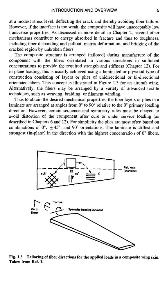
INTRODUCTION AND OVERVIEW 5 at a modest stress level,deflecting the crack and thereby avoiding fiber failure. However,if the interface is too weak,the composite will have unacceptably low transverse properties.As discussed in more detail in Chapter 2,several other mechanisms contribute to energy absorbed in fracture and thus to toughness, including fiber disbonding and pullout,matrix deformation,and bridging of the cracked region by unbroken fibers. The composite structure is arranged (tailored)during manufacture of the component with the fibers orientated in various directions in sufficient concentrations to provide the required strength and stiffness(Chapter 12).For in-plane loading,this is usually achieved using a laminated or plywood type of construction consisting of layers or plies of unidirectional or bi-directional orientated fibers.This concept is illustrated in Figure 1.3 for an aircraft wing. Alternatively,the fibers may be arranged by a variety of advanced textile techniques,such as weaving,braiding,or filament winding. Thus to obtain the desired mechanical properties,the fiber layers or plies in a laminate are arranged at angles from 0 to 90 relative to the 0 primary loading direction.However,certain sequence and symmetry rules must be obeyed to avoid distortion of the component after cure or under service loading (as described in Chapters 6 and 12).For simplicity the plies are most often based on combinations of0°,±45°,and90°orientations.The laminate is stiffest and strongest(in-plane)in the direction with the highest concentratio of 0 fibers, Ref.Axis (spanwise) Torque Spanwise bending moment Shear Fig.1.3 Tailoring of fiber directions for the applied loads in a composite wing skin Taken from Ref.1.INTRODUCTION AND OVERVIEW 5 at a modest stress level, deflecting the crack and thereby avoiding fiber failure. However, if the interface is too weak, the composite will have unacceptably low transverse properties. As discussed in more detail in Chapter 2, several other mechanisms contribute to energy absorbed in fracture and thus to toughness, including fiber disbonding and pullout, matrix deformation, and bridging of the cracked region by unbroken fibers. The composite structure is arranged (tailored) during manufacture of the component with the fibers orientated in various directions in sufficient concentrations to provide the required strength and stiffness (Chapter 12). For in-plane loading, this is usually achieved using a laminated or plywood type of construction consisting of layers or plies of unidirectional or bi-directional orientated fibers. This concept is illustrated in Figure 1.3 for an aircraft wing. Alternatively, the fibers may be arranged by a variety of advanced textile techniques, such as weaving, braiding, or filament winding. Thus to obtain the desired mechanical properties, the fiber layers or plies in a laminate are arranged at angles from 0 ° to 90 ° relative to the 0 ° primary loading direction. However, certain sequence and symmetry rules must be obeyed to avoid distortion of the component after cure or under service loading (as described in Chapters 6 and 12). For simplicity the plies are most often based on combinations of 0 °, + 45 °, and 90 ° orientations. The laminate is ~tiffest and strongest (in-plane) in the direction with the highest concentratio'~ of 0 ° fibers, Ref. Axis (spanwtse) ~-~ Torque Vertk Sheer Fig. 1.3 Tailoring of fiber directions for the applied loads in a composite wing skin. Taken from Ref. 1