正在加载图片...
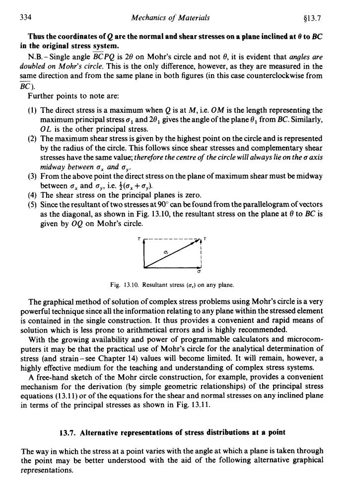
334 Mechanics of Materials §13.7 Thus the coordinates of Q are the normal and shear stresses on a plane inclined at 0 to BC in the original stress system. N.B.-Single angle BCPO is 20 on Mohr's circle and not 0,it is evident that angles are doubled on Mohr's circle.This is the only difference,however,as they are measured in the same direction and from the same plane in both figures (in this case counterclockwise from BC). Further points to note are: (1)The direct stress is a maximum when O is at M,i.e.OM is the length representing the maximum principal stresso;and 20,gives the angle of the plane from BC.Similarly, OL is the other principal stress. (2)The maximum shear stress is given by the highest point on the circle and is represented by the radius of the circle.This follows since shear stresses and complementary shear stresses have the same value;therefore the centre of the circle will always lie on the a axis midway between a.and a,. (3)From the above point the direct stress on the plane of maximum shear must be midway between a,and a,,i.e.(x+,). (4)The shear stress on the principal planes is zero. (5)Since the resultant of two stresses at 90can be found from the parallelogram of vectors as the diagonal,as shown in Fig.13.10,the resultant stress on the plane at 0 to BC is given by 00 on Mohr's circle. Fig.13.10.Resultant stress (a,)on any plane. The graphical method of solution of complex stress problems using Mohr's circle is a very powerful technique since all the information relating to any plane within the stressed element is contained in the single construction.It thus provides a convenient and rapid means of solution which is less prone to arithmetical errors and is highly recommended. With the growing availability and power of programmable calculators and microcom- puters it may be that the practical use of Mohr's circle for the analytical determination of stress (and strain-see Chapter 14)values will become limited.It will remain,however,a highly effective medium for the teaching and understanding of complex stress systems. A free-hand sketch of the Mohr circle construction,for example,provides a convenient mechanism for the derivation (by simple geometric relationships)of the principal stress equations(13.11)or of the equations for the shear and normal stresses on any inclined plane in terms of the principal stresses as shown in Fig.13.11. 13.7.Alternative representations of stress distributions at a point The way in which the stress at a point varies with the angle at which a plane is taken through the point may be better understood with the aid of the following alternative graphical representations.334 Mechanics of Materials 613.7 Thus the coordinates of Q are the normal and shear stresses on a plane inclined at 8 to BC in the original stress system. N.B.-Single angle ZPQ is 28 on Mohr’s circle and not 8, it is evident that angles are doubled on Mohr’s circle. This is the only difference, however, as they are measured in the same direction and from the same plane in both figures (in this case counterclockwise from BC ). - Further points to note are: (1) The direct stress is a maximum when Q is at M, i.e. OM is the length representing the maximum principal stress a1 and 28, gives the angle of the plane 8, from BC. Similarly, OL is the other principal stress. (2) The maximum shear stress is given by the highest point on the circle and is represented by the radius of the circle. This follows since shear stresses and complementary shear stresses have the same value; therefore the centre of the circle will always lie on the a axis midway between a, and a,. (3) From the above point the direct stress on the plane of maximum shear must be midway between a, and a,,, i.e. $(a, + a,). (4) The shear stress on the principal planes is zero. (5) Since the resultant of two stresses at 90” can be found from the parallelogram of vectors as the diagonal, as shown in Fig. 13.10, the resultant stress on the plane at 8 to BC is given by OQ on Mohr’s circle. Fig. 13.10. Resultant stress (8,) on any plane. The graphical method of solution of complex stress problems using Mohr’s circle is a very powerful technique since all the information relating to any plane within the stressed element is contained in the single construction. It thus provides a convenient and rapid means of solution which is less prone to arithmetical errors and is highly recommended. With the growing availability and power of programmable calculators and microcomputers it may be that the practical use of Mohr’s circle for the analytical determination of stress (and strain-see Chapter 14) values will become limited. It will remain, however, a highly effective medium for the teaching and understanding of complex stress systems. A free-hand sketch of the Mohr circle construction, for example, provides a convenient mechanism for the derivation (by simple geometric relationships) of the principal stress equations (13.1 1) or of the equations for the shear and normal stresses on any inclined plane in terms of the principal stresses as shown in Fig. 13.11. 13.7. Alternative representations of stress distributions at a point The way in which the stress at a point vanes with the angle at which a plane is taken through the point may be better understood with the aid of the following alternative graphical representations