正在加载图片...
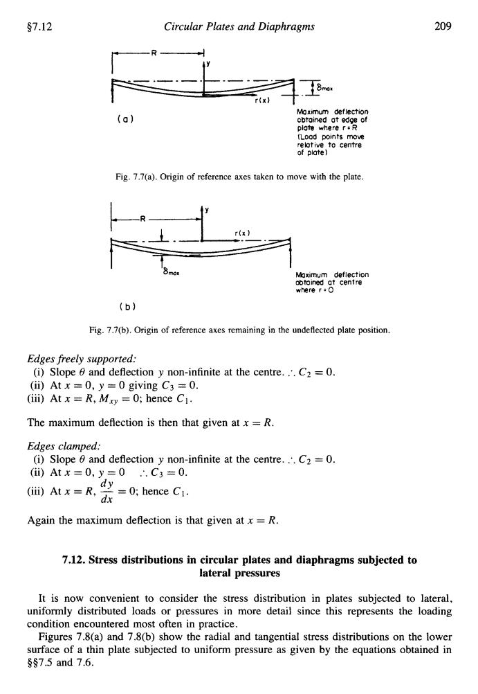
§7.12 Circular Plates and Diaphragms 209 Moximum deflection (a】 cbtained at edge of plote where r:R (Lood points move relotive to centre of plate) Fig.7.7(a).Origin of reference axes taken to move with the plate. r(x Maximum deflection obtoined at centre where r:O (b) Fig.7.7(b).Origin of reference axes remaining in the undeflected plate position. Edges freely supported: (i)Slope 6 and deflection y non-infinite at the centre..'.C2 =0. (ii)Atx=0,y=0 giving C3 =0. (iii)At x =R,Mry =0;hence C1. The maximum deflection is then that given at x =R. Edges clamped: (i)Slope 0 and deflection y non-infinite at the centre...C2=0. (i)Atx=0,y=0.C3=0. (iui)t0;hence Ci. Again the maximum deflection is that given at x=R. 7.12.Stress distributions in circular plates and diaphragms subjected to lateral pressures It is now convenient to consider the stress distribution in plates subjected to lateral, uniformly distributed loads or pressures in more detail since this represents the loading condition encountered most often in practice. Figures 7.8(a)and 7.8(b)show the radial and tangential stress distributions on the lower surface of a thin plate subjected to uniform pressure as given by the equations obtained in s§7.5and7.6.97.12 Circular Plates and Diaphragms 209 (a) Maximum deflection obtoined ot edge of plate where r : R (Load points move rebtive to centre of plate ) Fig. 7.7(a). Origin of reference axes taken to move with the plate. Maximum deflection obtained ot centre where r : 0 Fig. 7.7(b). Origin of reference axes remaining in the undeflected plate position. Edges freely supported: (i) Slope Q and deflection y non-infinite at the centre. :. C2 = 0. (ii) At x = 0, y = 0 giving C3 = 0. (iii) At x = R, M,, = 0; hence C1. The maximum deflection is then that given at x = R. Edges clamped: (i) Slope Q and deflection y non-infinite at the centre. :. C2 = 0. (ii) At x = 0, y = 0 :. C3 = 0. (iii) At x = R, - = 0; hence CI. dx Again the maximum deflection is that given at x = R. dY 7.12. Stress distributions in circular plates and diaphragms subjected to lateral pressures It is now convenient to consider the stress distribution in plates subjected to lateral, uniformly distributed loads or pressures in more detail since this represents the loading condition encountered most often in practice. Figures 7.8(a) and 7.8(b) show the radial and tangential stress distributions on the lower surface of a thin plate subjected to uniform pressure as given by the equations obtained in 997.5 and 7.6