正在加载图片...
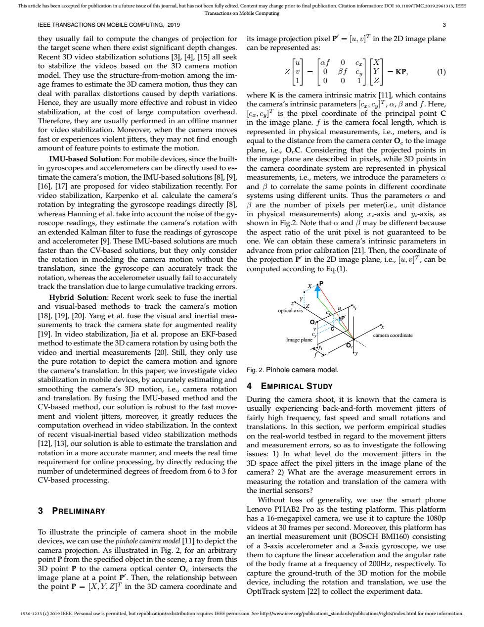
This article has been accepted for publication in a future issue of this journal,but has not been fully edited.Content may change prior to final publication.Citation information:DOI 10.1109/TMC.2019.2961313.IEEE Transactions on Mobile Computing IEEE TRANSACTIONS ON MOBILE COMPUTING.2019 3 they usually fail to compute the changes of projection for its image projection pixel P'=[u,v]T in the 2D image plane the target scene when there exist significant depth changes. can be represented as: Recent 3D video stabilization solutions [3],[4],[15]all seek to stabilize the videos based on the 3D camera motion model.They use the structure-from-motion among the im- KP (1) age frames to estimate the 3D camera motion,thus they can deal with parallax distortions caused by depth variations. where K is the camera intrinsic matrix [111,which contains Hence,they are usually more effective and robust in video the camera's intrinsic parametersBand f.Here, stabilization,at the cost of large computation overhead. is the pixel coordinate of the principal point C Therefore,they are usually performed in an offline manner in the image plane.f is the camera focal length,which is for video stabilization.Moreover,when the camera moves represented in physical measurements,i.e.,meters,and is fast or experiences violent jitters,they may not find enough equal to the distance from the camera center O.to the image amount of feature points to estimate the motion. plane,i.e.,OeC.Considering that the projected points in IMU-based Solution:For mobile devices,since the built- the image plane are described in pixels,while 3D points in in gyroscopes and accelerometers can be directly used to es- the camera coordinate system are represented in physical timate the camera's motion,the IMU-based solutions [8,[91, measurements,i.e.,meters,we introduce the parameters a [16],[17]are proposed for video stabilization recently.For and B to correlate the same points in different coordinate video stabilization,Karpenko et al.calculate the camera's systems using different units.Thus the parameters a and rotation by integrating the gyroscope readings directly [81,B are the number of pixels per meter(i.e.,unit distance whereas Hanning et al.take into account the noise of the gy- in physical measurements)along zi-axis and yi-axis,as roscope readings,they estimate the camera's rotation with shown in Fig.2.Note that a and B may be different because an extended Kalman filter to fuse the readings of gyroscope the aspect ratio of the unit pixel is not guaranteed to be and accelerometer [9].These IMU-based solutions are much one.We can obtain these camera's intrinsic parameters in faster than the CV-based solutions,but they only consider advance from prior calibration [21].Then,the coordinate of the rotation in modeling the camera motion without the the projection P'in the 2D image plane,i.e.,[u,v]T,can be translation,since the gyroscope can accurately track the computed according to Eq.(1) rotation,whereas the accelerometer usually fail to accurately track the translation due to large cumulative tracking errors. Hybrid Solution:Recent work seek to fuse the inertial and visual-based methods to track the camera's motion optic [18],[19],[20].Yang et al.fuse the visual and inertial mea- surements to track the camera state for augmented reality [19].In video stabilization,Jia et al.propose an EKF-based method to estimate the 3D camera rotation by using both the video and inertial measurements [201.Still,they only use the pure rotation to depict the camera motion and ignore the camera's translation.In this paper,we investigate video Fig.2.Pinhole camera model stabilization in mobile devices,by accurately estimating and smoothing the camera's 3D motion,i.e.,camera rotation A EMPIRICAL STUDY and translation.By fusing the IMU-based method and the During the camera shoot,it is known that the camera is CV-based method,our solution is robust to the fast move- usually experiencing back-and-forth movement jitters of ment and violent jitters,moreover,it greatly reduces the fairly high frequency,fast speed and small rotations and computation overhead in video stabilization.In the context translations.In this section,we perform empirical studies of recent visual-inertial based video stabilization methods on the real-world testbed in regard to the movement jitters [12],[13,our solution is able to estimate the translation and and measurement errors,so as to investigate the following rotation in a more accurate manner,and meets the real time issues:1)In what level do the movement jitters in the requirement for online processing,by directly reducing the 3D space affect the pixel jitters in the image plane of the number of undetermined degrees of freedom from 6 to 3 for camera?2)What are the average measurement errors in CV-based processing. measuring the rotation and translation of the camera with the inertial sensors? Without loss of generality,we use the smart phone 3 PRELIMINARY Lenovo PHAB2 Pro as the testing platform.This platform has a 16-megapixel camera,we use it to capture the 1080p To illustrate the principle of camera shoot in the mobile videos at 30 frames per second.Moreover,this platform has devices,we can use the pinhole camera model [11]to depict the an inertial measurement unit(BOSCH BMI160)consisting camera projection.As illustrated in Fig.2,for an arbitrary of a 3-axis accelerometer and a 3-axis gyroscope,we use point P from the specified object in the scene,a ray from this them to capture the linear acceleration and the angular rate 3D point P to the camera optical center Oc intersects the of the body frame at a frequency of 200Hz,respectively.To image plane at a point P.Then,the relationship between capture the ground-truth of the 3D motion for the mobile the point P=[X,Y,Z]T in the 3D camera coordinate and device,including the rotation and translation,we use the OptiTrack system [22]to collect the experiment data 1536-1233(c)2019 IEEE Personal use is permitted,but republication/redistribution requires IEEE permission.See http://www.ieee.org/publications_standards/publications/rights/index.html for more information.1536-1233 (c) 2019 IEEE. Personal use is permitted, but republication/redistribution requires IEEE permission. See http://www.ieee.org/publications_standards/publications/rights/index.html for more information. This article has been accepted for publication in a future issue of this journal, but has not been fully edited. Content may change prior to final publication. Citation information: DOI 10.1109/TMC.2019.2961313, IEEE Transactions on Mobile Computing IEEE TRANSACTIONS ON MOBILE COMPUTING, 2019 3 they usually fail to compute the changes of projection for the target scene when there exist significant depth changes. Recent 3D video stabilization solutions [3], [4], [15] all seek to stabilize the videos based on the 3D camera motion model. They use the structure-from-motion among the image frames to estimate the 3D camera motion, thus they can deal with parallax distortions caused by depth variations. Hence, they are usually more effective and robust in video stabilization, at the cost of large computation overhead. Therefore, they are usually performed in an offline manner for video stabilization. Moreover, when the camera moves fast or experiences violent jitters, they may not find enough amount of feature points to estimate the motion. IMU-based Solution: For mobile devices, since the builtin gyroscopes and accelerometers can be directly used to estimate the camera’s motion, the IMU-based solutions [8], [9], [16], [17] are proposed for video stabilization recently. For video stabilization, Karpenko et al. calculate the camera’s rotation by integrating the gyroscope readings directly [8], whereas Hanning et al. take into account the noise of the gyroscope readings, they estimate the camera’s rotation with an extended Kalman filter to fuse the readings of gyroscope and accelerometer [9]. These IMU-based solutions are much faster than the CV-based solutions, but they only consider the rotation in modeling the camera motion without the translation, since the gyroscope can accurately track the rotation, whereas the accelerometer usually fail to accurately track the translation due to large cumulative tracking errors. Hybrid Solution: Recent work seek to fuse the inertial and visual-based methods to track the camera’s motion [18], [19], [20]. Yang et al. fuse the visual and inertial measurements to track the camera state for augmented reality [19]. In video stabilization, Jia et al. propose an EKF-based method to estimate the 3D camera rotation by using both the video and inertial measurements [20]. Still, they only use the pure rotation to depict the camera motion and ignore the camera’s translation. In this paper, we investigate video stabilization in mobile devices, by accurately estimating and smoothing the camera’s 3D motion, i.e., camera rotation and translation. By fusing the IMU-based method and the CV-based method, our solution is robust to the fast movement and violent jitters, moreover, it greatly reduces the computation overhead in video stabilization. In the context of recent visual-inertial based video stabilization methods [12], [13], our solution is able to estimate the translation and rotation in a more accurate manner, and meets the real time requirement for online processing, by directly reducing the number of undetermined degrees of freedom from 6 to 3 for CV-based processing. 3 PRELIMINARY To illustrate the principle of camera shoot in the mobile devices, we can use the pinhole camera model [11] to depict the camera projection. As illustrated in Fig. 2, for an arbitrary point P from the specified object in the scene, a ray from this 3D point P to the camera optical center Oc intersects the image plane at a point P 0 . Then, the relationship between the point P = [X, Y, Z] T in the 3D camera coordinate and its image projection pixel P 0 = [u, v] T in the 2D image plane can be represented as: Z u v 1 = αf 0 cx 0 βf cy 0 0 1 X Y Z = KP, (1) where K is the camera intrinsic matrix [11], which contains the camera’s intrinsic parameters [cx, cy] T , α, β and f. Here, [cx, cy] T is the pixel coordinate of the principal point C in the image plane. f is the camera focal length, which is represented in physical measurements, i.e., meters, and is equal to the distance from the camera center Oc to the image plane, i.e., OcC. Considering that the projected points in the image plane are described in pixels, while 3D points in the camera coordinate system are represented in physical measurements, i.e., meters, we introduce the parameters α and β to correlate the same points in different coordinate systems using different units. Thus the parameters α and β are the number of pixels per meter(i.e., unit distance in physical measurements) along xi-axis and yi-axis, as shown in Fig.2. Note that α and β may be different because the aspect ratio of the unit pixel is not guaranteed to be one. We can obtain these camera’s intrinsic parameters in advance from prior calibration [21]. Then, the coordinate of the projection P 0 in the 2D image plane, i.e., [u, v] T , can be computed according to Eq.(1). Image plane optical axis P P ′ C Oi Oc camera coordinate X Y Z z x y f xi yi v cy cx u Fig. 2. Pinhole camera model. 4 EMPIRICAL STUDY During the camera shoot, it is known that the camera is usually experiencing back-and-forth movement jitters of fairly high frequency, fast speed and small rotations and translations. In this section, we perform empirical studies on the real-world testbed in regard to the movement jitters and measurement errors, so as to investigate the following issues: 1) In what level do the movement jitters in the 3D space affect the pixel jitters in the image plane of the camera? 2) What are the average measurement errors in measuring the rotation and translation of the camera with the inertial sensors? Without loss of generality, we use the smart phone Lenovo PHAB2 Pro as the testing platform. This platform has a 16-megapixel camera, we use it to capture the 1080p videos at 30 frames per second. Moreover, this platform has an inertial measurement unit (BOSCH BMI160) consisting of a 3-axis accelerometer and a 3-axis gyroscope, we use them to capture the linear acceleration and the angular rate of the body frame at a frequency of 200Hz, respectively. To capture the ground-truth of the 3D motion for the mobile device, including the rotation and translation, we use the OptiTrack system [22] to collect the experiment data