正在加载图片...

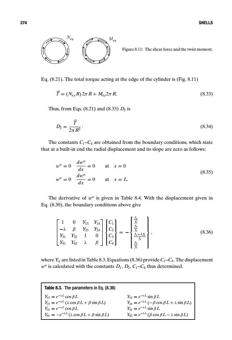
374 SHELLS Figure 8.11:The shear force and the twist moment. Eq.(8.21).The total torque acting at the edge of the cylinder is(Fig.8.11) =(Nsy R)27R+Mxy2n R. (8.33) Thus,from Eqs.(8.21)and (8.33)D2 is D2=2R (8.34) The constants C-Ca are obtained from the boundary conditions,which state that at a built-in end the radial displacement and its slope are zero as follows: dw w°=0 =0 atx=0 dx dwo (8.35) w°=0 =0 atx=L. dx The derivative of wo is given in Table 8.4.With the displacement given in Eq.(8.30),the boundary conditions above give 4 1 0 Y13 -入 B Y3 4 f+Lfs (8.36) 31 Y 0 C3 Y41 Yi where Yii are listed in Table 8.3.Equations(8.36)provide C1-C4.The displacement w is calculated with the constants D,D,C-C thus determined. Table 8.3.The parameters in Eq.(8.36) Yis =e-AL cos BL Yia =e-AL sin BL Y =e-L cos BL+Bsin BL) Ya=e-L (-B cos BL+sin BL) Ys1=e-AL cos BL Ys2=e-AL sin BL Ya =-e-L cos BL+B sin BL) Y=eL (B cos BL-sin BL)374 SHELLS Nxy Mxy Figure 8.11: The shear force and the twist moment. Eq. (8.21). The total torque acting at the edge of the cylinder is (Fig. 8.11) T = (NxyR) 2π R + Mxy2π R. (8.33) Thus, from Eqs. (8.21) and (8.33) D2 is D2 = T 2π R2 . (8.34) The constants C1–C4 are obtained from the boundary conditions, which state that at a built-in end the radial displacement and its slope are zero as follows: wo = 0 dwo dx = 0 at x = 0 wo = 0 dwo dx = 0 at x = L. (8.35) The derivative of wo is given in Table 8.4. With the displacement given in Eq. (8.30), the boundary conditions above give 1 0 Y13 Y14 −λ β Y23 Y24 Y31 Y32 1 0 Y41 Y42 λ β C1 C2 C3 C4 = − f4 f3 f5 f3 f4+Lf5 f3 f5 f3 , (8.36) where Yi j are listed in Table 8.3. Equations (8.36) provide C1–C4. The displacement wo is calculated with the constants D1, D2, C1–C4 thus determined. Table 8.3. The parameters in Eq. (8.36) Y13 = e−λL cos βL Y14 = e−λL sin βL Y23 = e−λL (λ cos βL+ β sin βL) Y24 = e−λL (−β cos βL+ λ sin βL) Y31 = e−λL cos βL Y32 = e−λL sin βL Y41 = −e−λL (λ cos βL+ β sin βL) Y42 = e−λL (β cos βL− λ sin βL)