正在加载图片...

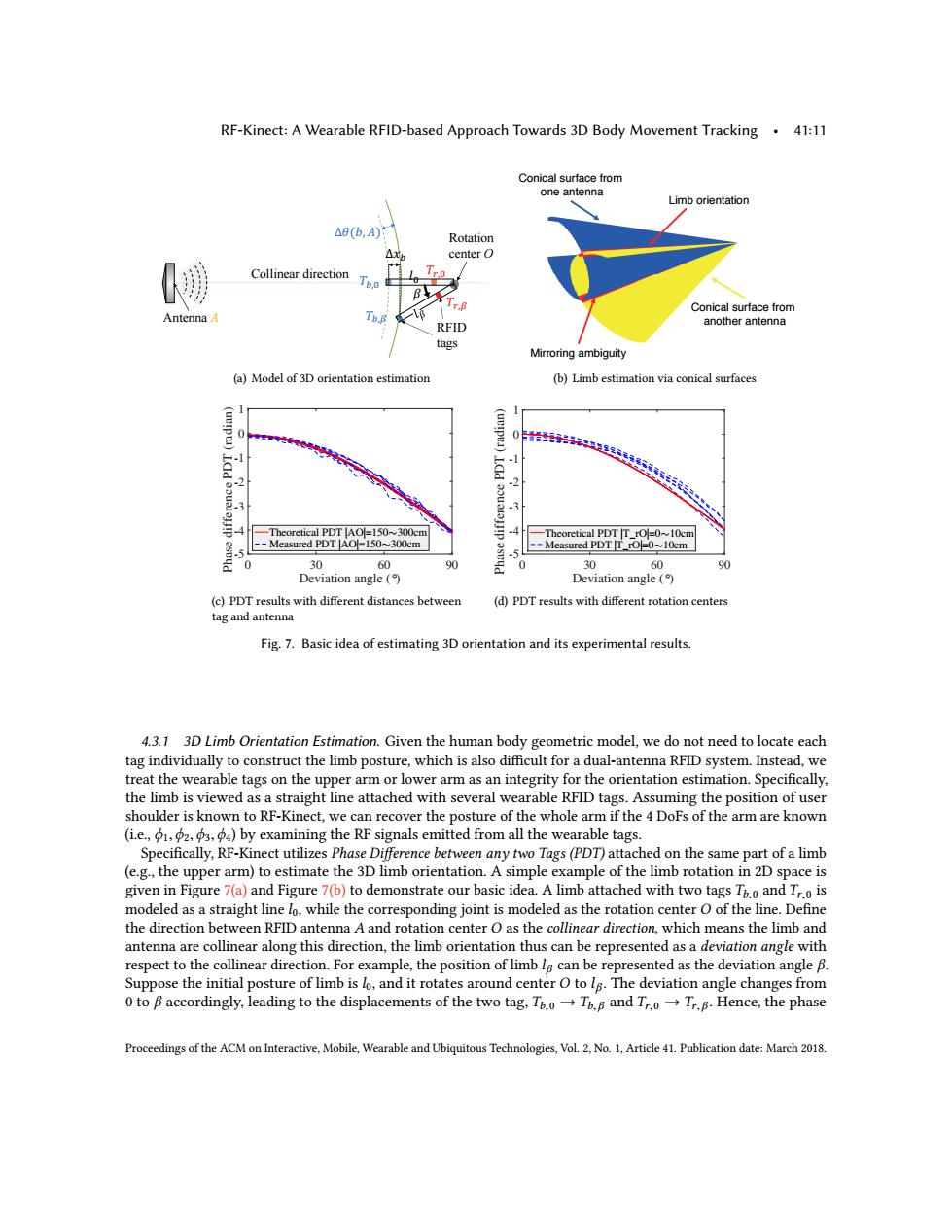
RF-Kinect:A Wearable RFID-based Approach Towards 3D Body Movement Tracking.41:11 Conical surface from one antenna Limb orientation △8(b,A) Rotation center O Collinear direction Tro B Tr.8 Conical surface from AntennaA Tb.B RFID another antenna tags Mirroring ambiguity (a)Model of 3D orientation estimation (b)Limb estimation via conical surfaces 0非35飞6及3 -2 -3 4 Theoretical PDT AO=150~300cm 4 -Theoretical PDT T_rO=0~10cm -Measured PDT [AO=150~300cm --Measured PDT T rO=0~10cm .5 0 30 60 % 0 30 60 % Deviation angle Deviation angle ( (c)PDT results with different distances between (d)PDT results with different rotation centers tag and antenna Fig.7.Basic idea of estimating 3D orientation and its experimental results. 4.3.1 3D Limb Orientation Estimation.Given the human body geometric model,we do not need to locate each tag individually to construct the limb posture,which is also difficult for a dual-antenna RFID system.Instead,we treat the wearable tags on the upper arm or lower arm as an integrity for the orientation estimation.Specifically, the limb is viewed as a straight line attached with several wearable RFID tags.Assuming the position of user shoulder is known to RF-Kinect,we can recover the posture of the whole arm if the 4 DoFs of the arm are known (i.e.,1.2.3,by examining the RF signals emitted from all the wearable tags. Specifically,RF-Kinect utilizes Phase Difference between any two Tags(PDT)attached on the same part of a limb (e.g.,the upper arm)to estimate the 3D limb orientation.A simple example of the limb rotation in 2D space is given in Figure 7(a)and Figure 7(b)to demonstrate our basic idea.A limb attached with two tags T6.o and Tr.o is modeled as a straight line lo,while the corresponding joint is modeled as the rotation center O of the line.Define the direction between RFID antenna A and rotation center O as the collinear direction,which means the limb and antenna are collinear along this direction,the limb orientation thus can be represented as a deviation angle with respect to the collinear direction.For example,the position of limb le can be represented as the deviation angle B. Suppose the initial posture of limb is lo,and it rotates around center O to lg.The deviation angle changes from 0 to B accordingly,leading to the displacements of the two tag,T.oT.B and Tr.oTr.B.Hence,the phase Proceedings of the ACM on Interactive,Mobile,Wearable and Ubiquitous Technologies,Vol.2,No.1,Article 41.Publication date:March 2018.RF-Kinect: A Wearable RFID-based Approach Towards 3D Body Movement Tracking • 41:11 ! "#$%& '( Antenna ' RFID tags Collinear direction Rotation ")* center O - +, *&, -.&, -.&/ -*&/ (a) Model of 3D orientation estimation Conical surface from one antenna Conical surface from another antenna Limb orientation Mirroring ambiguity (b) Limb estimation via conical surfaces Deviation angle (°) 0 30 60 90 Phase difference PDT (radian) -5 -4 -3 -2 -1 0 1 Theoretical PDT |AO|=150∼300cm Measured PDT |AO|=150∼300cm (c) PDT results with different distances between tag and antenna Deviation angle (°) 0 30 60 90 Phase difference PDT (radian) -5 -4 -3 -2 -1 0 1 Theoretical PDT |T_rO|=0∼10cm Measured PDT |T_rO|=0∼10cm (d) PDT results with different rotation centers Fig. 7. Basic idea of estimating 3D orientation and its experimental results. 4.3.1 3D Limb Orientation Estimation. Given the human body geometric model, we do not need to locate each tag individually to construct the limb posture, which is also difficult for a dual-antenna RFID system. Instead, we treat the wearable tags on the upper arm or lower arm as an integrity for the orientation estimation. Specifically, the limb is viewed as a straight line attached with several wearable RFID tags. Assuming the position of user shoulder is known to RF-Kinect, we can recover the posture of the whole arm if the 4 DoFs of the arm are known (i.e., ϕ1,ϕ2,ϕ3,ϕ4) by examining the RF signals emitted from all the wearable tags. Specifically, RF-Kinect utilizes Phase Difference between any two Tags (PDT) attached on the same part of a limb (e.g., the upper arm) to estimate the 3D limb orientation. A simple example of the limb rotation in 2D space is given in Figure 7(a) and Figure 7(b) to demonstrate our basic idea. A limb attached with two tags Tb,0 and Tr,0 is modeled as a straight line l0, while the corresponding joint is modeled as the rotation center O of the line. Define the direction between RFID antenna A and rotation center O as the collinear direction, which means the limb and antenna are collinear along this direction, the limb orientation thus can be represented as a deviation angle with respect to the collinear direction. For example, the position of limb lβ can be represented as the deviation angle β. Suppose the initial posture of limb is l0, and it rotates around center O to lβ . The deviation angle changes from 0 to β accordingly, leading to the displacements of the two tag, Tb,0 → Tb, β and Tr,0 → Tr, β . Hence, the phase Proceedings of the ACM on Interactive, Mobile, Wearable and Ubiquitous Technologies, Vol. 2, No. 1, Article 41. Publication date: March 2018