正在加载图片...

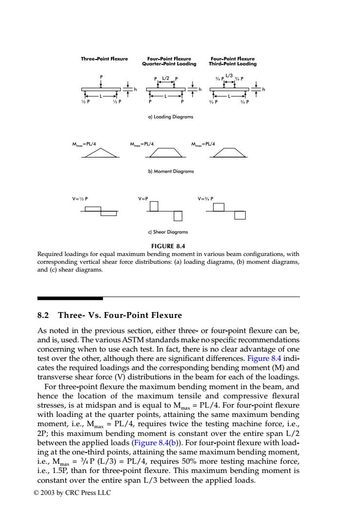
Three-Point Flexure Four-Point Flexure Four-Point Flexure Quarter-Point Loading Third-Point Loading 3 L/2 %P 3%P a)Loading Diagrams =PL/4 M-n=PL/4 Mn=PL/4 b)Moment Diogroms V=kP V-P V=%P c)Shear Diagrams FIGURE 8.4 Required loadings for equal maximum bending moment in various beam configurations,with corresponding vertical shear force distributions:(a)loading diagrams,(b)moment diagrams, and (c)shear diagrams. 8.2 Three-Vs.Four-Point Flexure As noted in the previous section,either three-or four-point flexure can be, and is,used.The various ASTM standards make no specific recommendations concerning when to use each test.In fact,there is no clear advantage of one test over the other,although there are significant differences.Figure 8.4 indi- cates the required loadings and the corresponding bending moment(M)and transverse shear force(V)distributions in the beam for each of the loadings. For three-point flexure the maximum bending moment in the beam,and hence the location of the maximum tensile and compressive flexural stresses,is at midspan and is equal to Mx=PL/4.For four-point flexure with loading at the quarter points,attaining the same maximum bending moment,i.e.,Mmax=PL/4,requires twice the testing machine force,i.e., 2P;this maximum bending moment is constant over the entire span L/2 between the applied loads(Figure 8.4(b)).For four-point flexure with load- ing at the one-third points,attaining the same maximum bending moment, i.e.,Mmax=3P (L/3)=PL/4,requires 50%more testing machine force, i.e.,1.5P,than for three-point flexure.This maximum bending moment is constant over the entire span L/3 between the applied loads. ©2003 by CRC Press LLC8.2 Three- Vs. Four-Point Flexure As noted in the previous section, either three- or four-point flexure can be, and is, used. The variousASTM standards make no specific recommendations concerning when to use each test. In fact, there is no clear advantage of one test over the other, although there are significant differences. Figure 8.4 indicates the required loadings and the corresponding bending moment (M) and transverse shear force (V) distributions in the beam for each of the loadings. For three-point flexure the maximum bending moment in the beam, and hence the location of the maximum tensile and compressive flexural stresses, is at midspan and is equal to Mmax = PL/4. For four-point flexure with loading at the quarter points, attaining the same maximum bending moment, i.e., Mmax = PL/4, requires twice the testing machine force, i.e., 2P; this maximum bending moment is constant over the entire span L/2 between the applied loads (Figure 8.4(b)). For four-point flexure with loading at the one-third points, attaining the same maximum bending moment, i.e., Mmax = 3 /4 P (L/3) = PL/4, requires 50% more testing machine force, i.e., 1.5P, than for three-point flexure. This maximum bending moment is constant over the entire span L/3 between the applied loads. FIGURE 8.4 Required loadings for equal maximum bending moment in various beam configurations, with corresponding vertical shear force distributions: (a) loading diagrams, (b) moment diagrams, and (c) shear diagrams. TX001_ch08_Frame Page 124 Saturday, September 21, 2002 4:59 AM © 2003 by CRC Press LLC