正在加载图片...
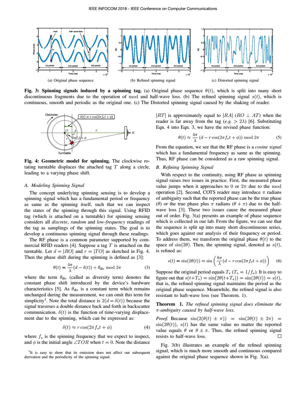
IEEE INFOCOM 2018-IEEE Conference on Computer Communications Y牡 2nd perio (a)Original phase sequence (b)Refined spinning signal (c)Distorted spinning signal Fig.3:Spinning signals induced by a spinning tag.(a)Original phase sequence 0(t),which is split into many short discontinuous fragments due to the operation of mod and half-wave loss.(b)The refined spinning signal s(t),which is continuous,smooth and periodic as the original one.(c)The Distorted spinning signal caused by the shaking of reader. 8(t)=rcos(2xfst+) RT is approximately equal to RA(RO L AT)when the reader is far away from the tag (e.g.>2A)[6].Substituting Eqn.4 into Eqn.3,we have the revised phase function: 9e0≈Fd-ros(2rft+o》mod2m (5) From the equation,we see that the RF phase is a cosine signal Turntable which has a fundamental frequency as same as the spinning. Fig.4:Geometric model for spinning.The clockwise ro- Thus,RF phase can be considered as a raw spinning signal. tating turntable displaces the attached tag T along a circle, B.Refining Spinning Signal leading to a varying phase shift. With respect to the continuity,using RF phase as spinning signal raises two issues in practice.First,the measured phase A.Modeling Spinning Signal value jumps when it approaches to 0 or 2m due to the mod The concept underlying spinning sensing is to develop a operation [2].Second,COTS reader may introduce m radians spinning signal which has a fundamental period or frequency of ambiguity such that the reported phase can be the true phase as same as the spinning itself,such that we can inspect (or the true phase plus radians (+due to the half- the states of the spinning through this signal.Using RFID wave loss [3].These two issues cause the measured phase tag (which is attached on a turntable)for spinning sensing out of order.Fig.3(a)presents an example of phase sequence considers all discrete,random and low-frequency readings of which is collected in our lab.From the figure,we can see that the tag as samplings of the spinning states.The goal is to the sequence is split up into many short discontinuous series, develop a continuous spinning signal through these readings. which goes against our analysis of their frequency or period. The RF phase is a common parameter supported by com- To address them,we transform the original phase 0(t)to the mercial RFID readers [4].Suppose a tag T is attached on the space of sin(20).Then,the spinning signal,denoted as s(t), turntable.Let d=|RO and r ITO]as sketched in Fig.4. is refined as: Then the phase shift during the spinning is defined as [3]: s()=sin(20()≈sin (6 ()d()+bax mod 2 (a-ros2ft+) (3) Suppose the original period equals T(T=1/fs).It is easy to where the term Odiv(called as diversity term)denotes the figure out that s(t+Ts)=sin(20(t+Ts))=sin(20(t))=s(t), constant phase shift introduced by the device's hardware that is,the refined spinning signal maintains the period as the characteristics [5].As 0div is a constant term which remains original phase sequence.Meanwhile,the refined signal is also unchanged during the measurement,we can omit this term for resistant to haft-wave loss (see Theorem.1). simplicity.Note the total distance is 2(d-6(t))because the signal traverses a double distance back and forth in backscatter Theorem 1.The refined spinning signal does eliminate the communication.o(t)is the function of time-varying displace- T-ambiguity caused by half-wave loss. ment due to the spinning,which can be expressed as: Proof.Because sin(2(θ(t)±π)=sin(29(t)±2r)= 6(t)≈rcos(2πfst+φ) (4) sin(20(t)),s(t)has the same value no matter the reported value equals 6 or 6+m.Thus,the refined spinning signal where f,is the spinning frequency that we expect to inspect,resists to half-wave loss. 口 and o is the initial angle TOR when t =0.Note the distance Fig.3(b)illustrates an example of the refined spinning IIt is easy to show that its omission does not affect our subsequent signal,which is much more smooth and continuous compared derivation and the periodicity of the spinning signal. against the original phase sequence shown in Fig.3(a).0 1 2 3 4 5 6 x 10⁴ −2 0 2 4 6 8 Time (ms) Phase (rad) mod π half−wave loss 1st period 2nd period 2π 3rd period (a) Original phase sequence 0 1 2 3 4 5 6 x 10⁴ −1.5 −1 −0.5 0 0.5 1 1.5 Time (ms) s(t) 1st period 2nd period 3rd period (b) Refined spinning signal 0 1 2 3 4 5 6 x 10⁴ −1.5 −1 −0.5 0 0.5 1 1.5 Time (ms) s(t) 1st period 2nd period 3rd period (c) Distorted spinning signal Fig. 3: Spinning signals induced by a spinning tag. (a) Original phase sequence ✓(t), which is split into many short discontinuous fragments due to the operation of mod and half-wave loss. (b) The refined spinning signal s(t), which is continuous, smooth and periodic as the original one. (c) The Distorted spinning signal caused by the shaking of reader. T Turntable Clockwise R O A d δ(t) = r cos(2⇡fst + φ) r 2⇡fst + φ Fig. 4: Geometric model for spinning. The clockwise rotating turntable displaces the attached tag T along a circle, leading to a varying phase shift. A. Modeling Spinning Signal The concept underlying spinning sensing is to develop a spinning signal which has a fundamental period or frequency as same as the spinning itself, such that we can inspect the states of the spinning through this signal. Using RFID tag (which is attached on a turntable) for spinning sensing considers all discrete, random and low-frequency readings of the tag as samplings of the spinning states. The goal is to develop a continuous spinning signal through these readings. The RF phase is a common parameter supported by commercial RFID readers [4]. Suppose a tag T is attached on the turntable. Let d = |RO| and r = |T O| as sketched in Fig. 4. Then the phase shift during the spinning is defined as [3]: ✓(t) = 4⇡ λ (d − δ(t)) + ✓div mod 2⇡ (3) where the term ✓div (called as diversity term) denotes the constant phase shift introduced by the device’s hardware characteristics [5]. As ✓div is a constant term which remains unchanged during the measurement, we can omit this term for simplicity1. Note the total distance is 2(d − δ(t)) because the signal traverses a double distance back and forth in backscatter communication. δ(t) is the function of time-varying displacement due to the spinning, which can be expressed as: δ(t) ⇡ r cos(2⇡fst + φ) (4) where fs is the spinning frequency that we expect to inspect, and φ is the initial angle \TOR when t = 0. Note the distance 1It is easy to show that its omission does not affect our subsequent derivation and the periodicity of the spinning signal. |RT| is approximately equal to |RA| (RO ? AT) when the reader is far away from the tag (e.g. > 2λ) [6]. Substituting Eqn. 4 into Eqn. 3, we have the revised phase function: ✓(t) ⇡ 4⇡ λ (d − r cos(2⇡fst + φ)) mod 2⇡ (5) From the equation, we see that the RF phase is a cosine signal which has a fundamental frequency as same as the spinning. Thus, RF phase can be considered as a raw spinning signal. B. Refining Spinning Signal With respect to the continuity, using RF phase as spinning signal raises two issues in practice. First, the measured phase value jumps when it approaches to 0 or 2⇡ due to the mod operation [2]. Second, COTS reader may introduce ⇡ radians of ambiguity such that the reported phase can be the true phase (✓) or the true phase plus ⇡ radians (✓ + ⇡) due to the halfwave loss [3]. These two issues cause the measured phase out of order. Fig. 3(a) presents an example of phase sequence which is collected in our lab. From the figure, we can see that the sequence is split up into many short discontinuous series, which goes against our analysis of their frequency or period. To address them, we transform the original phase ✓(t) to the space of sin(2✓). Then, the spinning signal, denoted as s(t), is refined as: s(t) = sin(2✓(t)) ⇡ sin ✓8⇡ λ (d − r cos(2⇡fst + φ))◆ (6) Suppose the original period equals Ts (Ts = 1/fs). It is easy to figure out that s(t+Ts) = sin(2✓(t+Ts)) = sin(2✓(t)) = s(t), that is, the refined spinning signal maintains the period as the original phase sequence. Meanwhile, the refined signal is also resistant to haft-wave loss (see Theorem. 1). Theorem 1. The refined spinning signal does eliminate the ⇡-ambiguity caused by half-wave loss. Proof. Because sin(2(✓(t) ± ⇡)) = sin(2✓(t) ± 2⇡) = sin(2✓(t)), s(t) has the same value no matter the reported value equals ✓ or ✓ ± ⇡. Thus, the refined spinning signal resists to half-wave loss. Fig. 3(b) illustrates an example of the refined spinning signal, which is much more smooth and continuous compared against the original phase sequence shown in Fig. 3(a). IEEE INFOCOM 2018 - IEEE Conference on Computer Communications