正在加载图片...

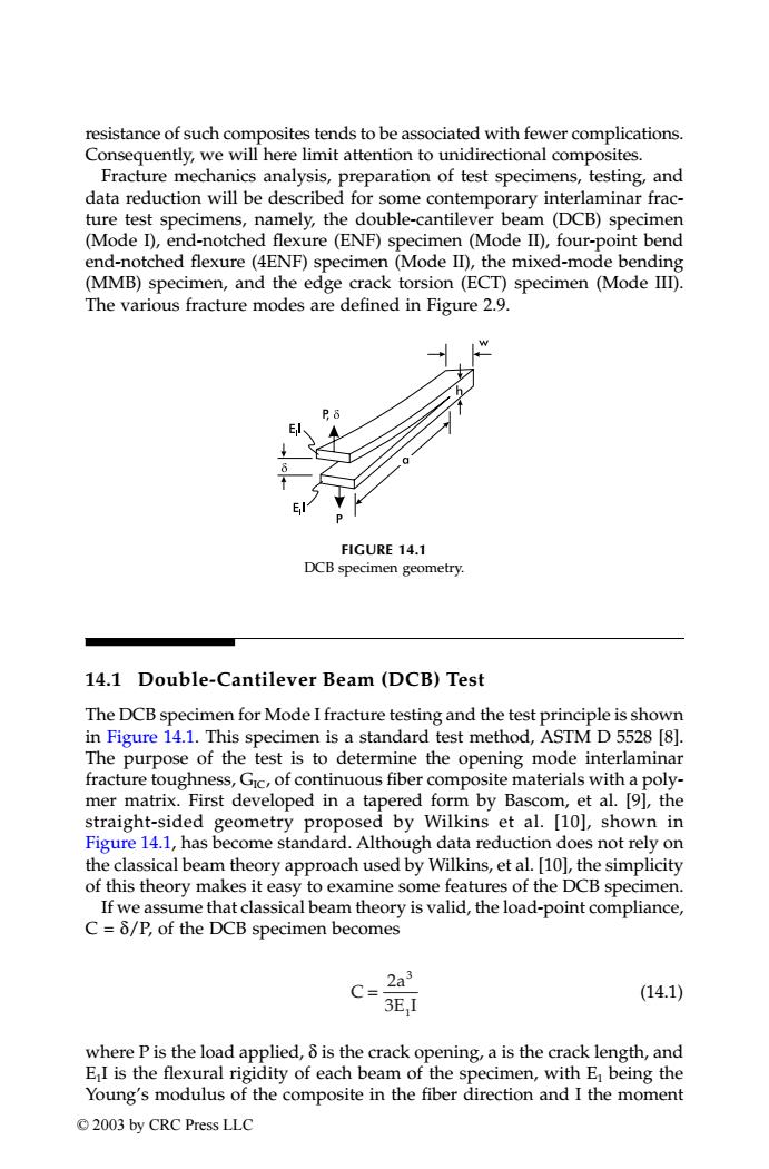
resistance of such composites tends to be associated with fewer complications. Consequently,we will here limit attention to unidirectional composites. Fracture mechanics analysis,preparation of test specimens,testing,and data reduction will be described for some contemporary interlaminar frac- ture test specimens,namely,the double-cantilever beam (DCB)specimen (Mode I),end-notched flexure (ENF)specimen (Mode II),four-point bend end-notched flexure(4ENF)specimen(Mode Il),the mixed-mode bending (MMB)specimen,and the edge crack torsion (ECT)specimen (Mode III). The various fracture modes are defined in Figure 2.9. FIGURE 14.1 DCB specimen geometry. 14.1 Double-Cantilever Beam (DCB)Test The DCB specimen for Mode I fracture testing and the test principle is shown in Figure 14.1.This specimen is a standard test method,ASTM D 5528[8]. The purpose of the test is to determine the opening mode interlaminar fracture toughness,Gic,of continuous fiber composite materials with a poly- mer matrix.First developed in a tapered form by Bascom,et al.[9],the straight-sided geometry proposed by Wilkins et al.[10],shown in Figure 14.1,has become standard.Although data reduction does not rely on the classical beam theory approach used by Wilkins,et al.[10],the simplicity of this theory makes it easy to examine some features of the DCB specimen. If we assume that classical beam theory is valid,the load-point compliance, C=8/P,of the DCB specimen becomes C= 2a3 (14.1) 3E,I where P is the load applied,6 is the crack opening,a is the crack length,and EI is the flexural rigidity of each beam of the specimen,with E being the Young's modulus of the composite in the fiber direction and I the moment ©2003 by CRC Press LLCresistance of such composites tends to be associated with fewer complications. Consequently, we will here limit attention to unidirectional composites. Fracture mechanics analysis, preparation of test specimens, testing, and data reduction will be described for some contemporary interlaminar fracture test specimens, namely, the double-cantilever beam (DCB) specimen (Mode I), end-notched flexure (ENF) specimen (Mode II), four-point bend end-notched flexure (4ENF) specimen (Mode II), the mixed-mode bending (MMB) specimen, and the edge crack torsion (ECT) specimen (Mode III). The various fracture modes are defined in Figure 2.9. 14.1 Double-Cantilever Beam (DCB) Test The DCB specimen for Mode I fracture testing and the test principle is shown in Figure 14.1. This specimen is a standard test method, ASTM D 5528 [8]. The purpose of the test is to determine the opening mode interlaminar fracture toughness, GIC, of continuous fiber composite materials with a polymer matrix. First developed in a tapered form by Bascom, et al. [9], the straight-sided geometry proposed by Wilkins et al. [10], shown in Figure 14.1, has become standard. Although data reduction does not rely on the classical beam theory approach used by Wilkins, et al. [10], the simplicity of this theory makes it easy to examine some features of the DCB specimen. If we assume that classical beam theory is valid, the load-point compliance, C = δ/P, of the DCB specimen becomes (14.1) where P is the load applied, δ is the crack opening, a is the crack length, and E1I is the flexural rigidity of each beam of the specimen, with E1 being the Young’s modulus of the composite in the fiber direction and I the moment FIGURE 14.1 DCB specimen geometry. C a E I = 2 3 3 1 TX001_ch14_Frame Page 186 Saturday, September 21, 2002 5:09 AM © 2003 by CRC Press LLC