正在加载图片...

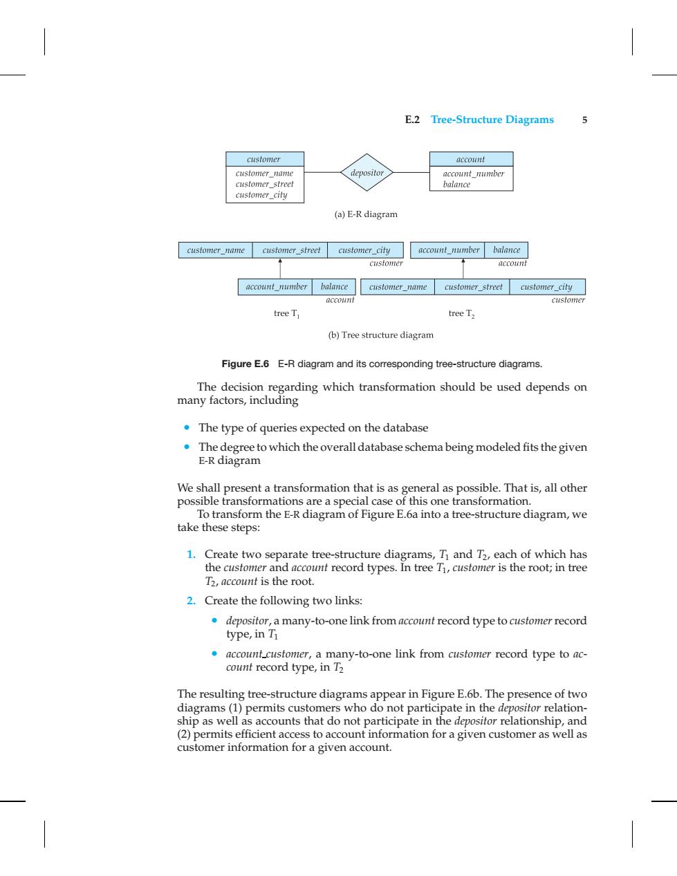
E.2 Tree-Structure Diagrams 5 customer account customer_name depositor account_number customer_street balance customer_city (a)E-R diagram customer_name customer street customer city account number balance customer account account number balance customer_name customer_street customer_city account customer treeT tree T2 (b)Tree structure diagram Figure E.6 E-R diagram and its corresponding tree-structure diagrams. The decision regarding which transformation should be used depends on many factors,including The type of queries expected on the database The degree to which the overall database schema being modeled fits the given E-R diagram We shall present a transformation that is as general as possible.That is,all other possible transformations are a special case of this one transformation. To transform the E-R diagram of Figure E.6a into a tree-structure diagram,we take these steps: 1.Create two separate tree-structure diagrams,Ti and T2,each of which has the customer and account record types.In tree Ti,customer is the root;in tree 1,account is the root. 2.Create the following two links: depositor,a many-to-one link from account record type to customer record type,in Ti account customer,a many-to-one link from customer record type to ac- count record type,in T2 The resulting tree-structure diagrams appear in Figure E.6b.The presence of two diagrams(1)permits customers who do not participate in the depositor relation- ship as well as accounts that do not participate in the depositor relationship,and (2)permits efficient access to account information for a given customer as well as customer information for a given account.E.2 Tree-Structure Diagrams 5 Figure E.6 E-R diagram and its corresponding tree-structure diagrams. The decision regarding which transformation should be used depends on many factors, including • The type of queries expected on the database • The degree to which the overall database schema being modeled fits the given E-R diagram We shall present a transformation that is as general as possible. That is, all other possible transformations are a special case of this one transformation. To transform the E-R diagram of Figure E.6a into a tree-structure diagram, we take these steps: 1. Create two separate tree-structure diagrams, T1 and T2, each of which has the customer and account record types. In tree T1, customer is the root; in tree T2, account is the root. 2. Create the following two links: • depositor, a many-to-one link from accountrecord type to customerrecord type, in T1 • account customer, a many-to-one link from customer record type to account record type, in T2 The resulting tree-structure diagrams appear in Figure E.6b. The presence of two diagrams (1) permits customers who do not participate in the depositor relationship as well as accounts that do not participate in the depositor relationship, and (2) permits efficient access to account information for a given customer as well as customer information for a given account