正在加载图片...
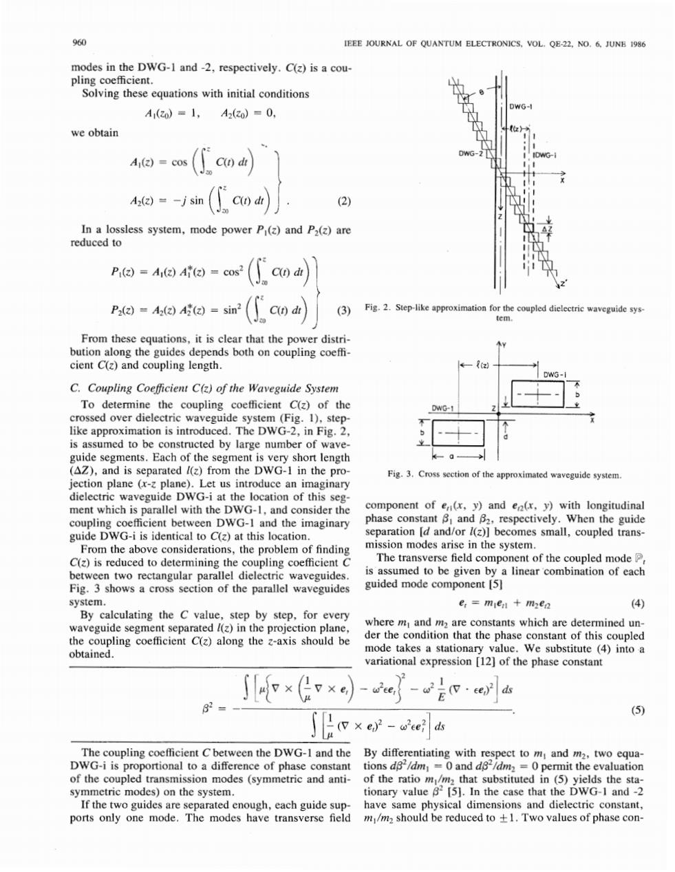
960 IEEE JOURNAL OF QUANTUM ELECTRONICS,VOL.QE-22.NO.6.JUNE 1986 modes in the DWG-I and-2,respectively.C(z)is a cou- pling coefficient. Solving these equations with initial conditions WG- A1(zo)=1, A2(20)=0, we obtain A1(z)=cos (2) In a lossless system,mode power P(z)and P2(z)are reduced to Pi()=A1(z)Ai(2)=cos (Gcon P2(z)=A2(z)A(z)=sin (3) Fig.2.Step-like approximation for the coupled dielectric waveguide sys- tem. From these equations,it is clear that the power distri- bution along the guides depends both on coupling coeffi- cient C(z)and coupling length. R(z) DWG-I C.Coupling Coefficient C(z)of the Waveguide System To determine the coupling coefficient C(z)of the DWG-1 crossed over dielectric waveguide system(Fig.1),step- like approximation is introduced.The DWG-2,in Fig.2, is assumed to be constructed by large number of wave- guide segments.Each of the segment is very short length (AZ),and is separated /(z)from the DWG-1 in the pro- Fig.3. Cross section of the approximated waveguide system. jection plane (x-z plane).Let us introduce an imaginary dielectric waveguide DWG-i at the location of this seg- ment which is parallel with the DWG-1,and consider the component of e(x,y)and en(r,y)with longitudinal coupling coefficient between DWG-1 and the imaginary phase constant B and B2,respectively.When the guide guide DWG-i is identical to C(z)at this location. separation [d and/or /(z)]becomes small,coupled trans- From the above considerations,the problem of finding mission modes arise in the system. C(z)is reduced to determining the coupling coefficient C The transverse field component of the coupled mode P between two rectangular parallel dielectric waveguides. is assumed to be given by a linear combination of each Fig.3 shows a cross section of the parallel waveguides guided mode component [5] system. er=men mzen (4) By calculating the C value,step by step,for every waveguide segment separated /(z)in the projection plane, where m and m2 are constants which are determined un- the coupling coefficient C(z)along the z-axis should be der the condition that the phase constant of this coupled obtained. mode takes a stationary value.We substitute (4)into a variational expression [12]of the phase constant ce, -2e ds 82 (5) x e)2-wee?ds The coupling coefficient C between the DWG-I and the By differentiating with respect to m:and m2,two equa- DWG-i is proportional to a difference of phase constant tions d82/dm=0 and d82/dm2=0 permit the evaluation of the coupled transmission modes (symmetric and anti- of the ratio m/mz that substituted in (5)yields the sta- symmetric modes)on the system. tionary value 82[5].In the case that the DWG-I and-2 If the two guides are separated enough,each guide sup- have same physical dimensions and dielectric constant, ports only one mode.The modes have transverse field m/mz should be reduced to +1.Two values of phase con-960 IEEE JOURNAL OF QUANTUM ELECTRONICS, VOL. QE-22, NO. 6, JUNE 1986 modes in the DWG-1 and -2, respectively. C(z) is a COUpling coefficient. Solving these equations with initial conditions A,(zo) = 1, MZO) = 0, we obtain In a lossless system, mode power Pl(z) and P2(z) are reduced to / PZ \ From these equations, it is clear that the power distribution along the guides depends both on coupling coefficient C(z) and coupling length. C. Coupling Coeflcient C(z) of the Waveguide System To determine the coupling coefficient C(z) of the crossed over dielectric waveguide system (Fig. 1), steplike approximation is introduced. The DWG-2, in Fig. 2, is assumed to be constructed by large number of waveguide segments. Each of the segment is very short length (AZ), and is separated Z(z) from the DWG-1 in the projection plane (x-z plane). Let us introduce an imaginary dielectric waveguide DWG-i at the location of this segment which is parallel with the DWG- 1 , and consider the coupling coefficient between DWG-1 and the imaginary guide DWG-i is identical to C(z) at this location. From the above considerations, the problem of finding C(z) is reduced to determining the coupling coefficient C between two rectangular parallel dielectric waveguides. Fig. 3 shows a cross section of the parallel waveguides system. By calculating the C value, step by step, for every waveguide segment separated Z(z) in the projection plane, the coupling coefficient C(z) along the z-axis should be obtained. Fig. 2. Step-like approximation for the coupled dielectric waveguide system. La-I I Fig. 3. Cross section of the approximated waveguide system. component of erl(x, y) and e&, y) with longitudinal phase constant PI and P2, respectively. When the guide separation [d and/or Z(z)] becomes small, coupled transmission modes arise in the system. The transverse field component of the coupled mode Pt is assumed to be given by a linear 'combination of each guided mode component [5] e, = mleIl + m2er2 (4) where ml and m2 are constants which are determined under the condition that the phase constant of this coupled mode takes a stationary value. We substitute (4) into a variational expression [12] of the phase constant - w Eel - w - (v . cer)2] ds E 21 The coupling coefficient C between the DWG- 1 and the DWG-i is proportional to a difference of phase constant of the coupled transmission modes (symmetric and antisymmetric modes) on the system. If the two guides are separated enough, each guide supports only one mode. The modes have transverse field By differentiating with respect to ml and m2, two equations dP2/drnl = 0 and dp2/dm2 = 0 permit the evaluation of the ratio m,/m2 that substituted in (5) yields the stationary value [5]. In the case that the DWG-1 and -2 have same physical dimensions and dielectric constant, ml/m2 should be reduced to + 1. Two values of phase con-