正在加载图片...
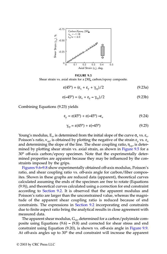
0.75 Carbon/Epoxy.[301s ny=-1.18 e/w=6.0 0.50 000..0.0 0.25 00-0000000 0 0.10.20.30.4 0.5 Axial Strain ()deg- FIGURE 9.5 Shear strain vs.axial strain for a [30l carbon/epoxy composite. e(45)=(ex+E,+Yy)/2 (9.23a) -45)=(e+8y-Yy)/2 (9.23b) Combining Equations (9.23)yields 8,=e(45)+c(-45)-e (9.24) Yy=e(45)+e(-45) (9.25) Young's modulus,E is determined from the initial slope of the curve ox vs.E Poisson's ratio,v is obtained by plotting the negative of the strain E vs. and determining the slope of the line.The shear coupling ratio,nxy is deter- mined by plotting shear strain vs.axial strain,as shown in Figure 9.5 for a 30 off-axis carbon/epoxy specimen.Note that the experimentally deter- mined properties are apparent because they may be influenced by the con- straints imposed by the grips. Figures 9.6-9.8 show experimentally obtained off-axis modulus,Poisson's ratio,and shear coupling ratio vs.off-axis angle for carbon/fiber compos- ites.Shown in these graphs are reduced data(apparent),theoretical curves calculated assuming the ends of the specimen are free to rotate(Equations (9.9)),and theoretical curves calculated using a correction for end constraint according to Section 9.2.It is observed that the apparent modulus and Poisson's ratio are larger than the unconstrained value,whereas the magni- tude of the apparent shear coupling ratio is reduced because of end constraints.The expressions in Section 9.2 incorporating end constraints due to finite aspect ratio bring the analytical results in close agreement with measured data. The apparent shear modulus,G2,determined for a carbon/polyimide com- posite using Equations (9.6)-(9.8)and corrected for shear stress and end constraint using Equation (9.20),is shown vs.off-axis angle in Figure 9.9. At off-axis angles up to 30 the end constraint will increase the apparent 2003 by CRC Press LLCε(45°) = (εx + εy + γxy)/2 (9.23a) ε(–45°) = (εx + εy – γxy)/2 (9.23b) Combining Equations (9.23) yields εy = ε(45°) + ε(–45°) –εx (9.24) γxy = ε(45°) + ε(–45°) (9.25) Young’s modulus, Ex, is determined from the initial slope of the curve σx vs. εx. Poisson’s ratio, νxy, is obtained by plotting the negative of the strain εy vs. εx and determining the slope of the line. The shear coupling ratio, ηxy, is determined by plotting shear strain vs. axial strain, as shown in Figure 9.5 for a 30° off-axis carbon/epoxy specimen. Note that the experimentally determined properties are apparent because they may be influenced by the constraints imposed by the grips. Figures 9.6–9.8 show experimentally obtained off-axis modulus, Poisson’s ratio, and shear coupling ratio vs. off-axis angle for carbon/fiber composites. Shown in these graphs are reduced data (apparent), theoretical curves calculated assuming the ends of the specimen are free to rotate (Equations (9.9)), and theoretical curves calculated using a correction for end constraint according to Section 9.2. It is observed that the apparent modulus and Poisson’s ratio are larger than the unconstrained value, whereas the magnitude of the apparent shear coupling ratio is reduced because of end constraints. The expressions in Section 9.2 incorporating end constraints due to finite aspect ratio bring the analytical results in close agreement with measured data. The apparent shear modulus, G12, determined for a carbon/polyimide composite using Equations (9.6) – (9.8) and corrected for shear stress and end constraint using Equation (9.20), is shown vs. off-axis angle in Figure 9.9. At off-axis angles up to 30° the end constraint will increase the apparent FIGURE 9.5 Shear strain vs. axial strain for a [30]6 carbon/epoxy composite. TX001_ch09_Frame Page 139 Saturday, September 21, 2002 5:01 AM © 2003 by CRC Press LLC