正在加载图片...
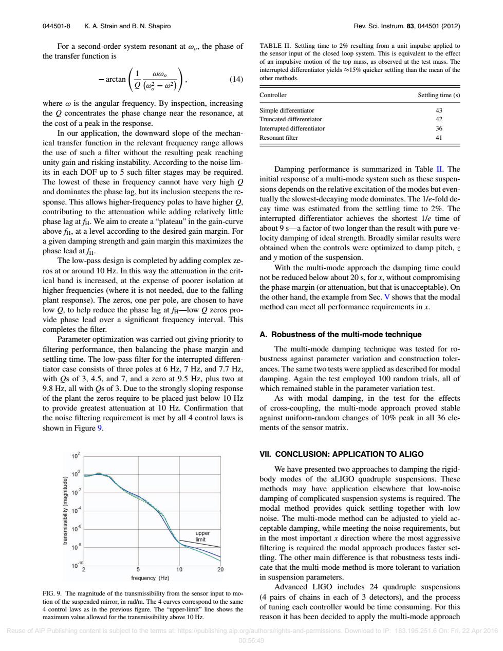
044501-8 K.A.Strain and B.N.Shapiro Rev.Sci.Instrum.83,044501(2012) For a second-order system resonant at o,the phase of TABLE II.Settling time to 2%resulting from a unit impulse applied to the transfer function is the sensor input of the closed loop system.This is equivalent to the effect of an impulsive motion of the top mass,as observed at the test mass.The interrupted differentiator yields%quicker settling than the mean of the arctan (14) other methods. 0(o-2 Controller Settling time(s) where is the angular frequency.By inspection,increasing the O concentrates the phase change near the resonance,at Simple differentiator 43 the cost of a peak in the response. Truncated differentiator 42 Interrupted differentiator 36 In our application,the downward slope of the mechan- Resonant filter 41 ical transfer function in the relevant frequency range allows the use of such a filter without the resulting peak reaching unity gain and risking instability.According to the noise lim- its in each DOF up to 5 such filter stages may be required. Damping performance is summarized in Table II.The The lowest of these in frequency cannot have very high O initial response of a multi-mode system such as these suspen- and dominates the phase lag,but its inclusion steepens the re- sions depends on the relative excitation of the modes but even- sponse.This allows higher-frequency poles to have higher O. tually the slowest-decaying mode dominates.The l/e-fold de- contributing to the attenuation while adding relatively little cay time was estimated from the settling time to 2%.The phase lag at fu.We aim to create a"plateau"in the gain-curve interrupted differentiator achieves the shortest l/e time of above fi,at a level according to the desired gain margin.For about 9 s-a factor of two longer than the result with pure ve- a given damping strength and gain margin this maximizes the locity damping of ideal strength.Broadly similar results were phase lead atfu. obtained when the controls were optimized to damp pitch, The low-pass design is completed by adding complex ze- and y motion of the suspension. ros at or around 10 Hz.In this way the attenuation in the crit- With the multi-mode approach the damping time could ical band is increased,at the expense of poorer isolation at not be reduced below about 20 s,for x,without compromising higher frequencies (where it is not needed,due to the falling the phase margin (or attenuation,but that is unacceptable).On plant response).The zeros,one per pole,are chosen to have the other hand,the example from Sec.V shows that the modal low O,to help reduce the phase lag at f-low O zeros pro- method can meet all performance requirements in x. vide phase lead over a significant frequency interval.This completes the filter. A.Robustness of the multi-mode technique Parameter optimization was carried out giving priority to filtering performance,then balancing the phase margin and The multi-mode damping technique was tested for ro- settling time.The low-pass filter for the interrupted differen- bustness against parameter variation and construction toler- tiator case consists of three poles at 6 Hz,7 Hz,and 7.7 Hz, ances.The same two tests were applied as described for modal with Os of 3,4.5,and 7,and a zero at 9.5 Hz,plus two at damping.Again the test employed 100 random trials,all of 9.8 Hz,all with Os of 3.Due to the strongly sloping response which remained stable in the parameter variation test. of the plant the zeros require to be placed just below 10 Hz As with modal damping,in the test for the effects to provide greatest attenuation at 10 Hz.Confirmation that of cross-coupling,the multi-mode approach proved stable the noise filtering requirement is met by all 4 control laws is against uniform-random changes of 10%peak in all 36 ele- shown in Figure 9. ments of the sensor matrix. 10 VIl.CONCLUSION:APPLICATION TO ALIGO 10 We have presented two approaches to damping the rigid- body modes of the aLIGO quadruple suspensions.These 10 methods may have application elsewhere that low-noise damping of complicated suspension systems is required.The 10 modal method provides quick settling together with low noise.The multi-mode method can be adjusted to yield ac- 10 ceptable damping,while meeting the noise requirements,but upper lmit in the most important x direction where the most aggressive 10 filtering is required the modal approach produces faster set- tling.The other main difference is that robustness tests indi- 10 2 与 10 cate that the multi-mode method is more tolerant to variation frequency (Hz) in suspension parameters. Advanced LIGO includes 24 quadruple suspensions FIG.9.The magnitude of the transmissibility from the sensor input to mo- tion of the suspended mirror,in rad/m.The 4 curves correspond to the same (4 pairs of chains in each of 3 detectors),and the process 4 control laws as in the previous figure.The"upper-limit"line shows the of tuning each controller would be time consuming.For this maximum value allowed for the transmissibility above 10 Hz. reason it has been decided to apply the multi-mode approach Reuse of AlP Publishing content is subject to the terms at:https://publishing.aip.org/authors/rights-and-permissions.Download to IP:183.195.251.6 On:Fri.22 Apr 2016 00:5549044501-8 K. A. Strain and B. N. Shapiro Rev. Sci. Instrum. 83, 044501 (2012) For a second-order system resonant at ωo, the phase of the transfer function is − arctan 1 Q ωωo ω2 o − ω2 , (14) where ω is the angular frequency. By inspection, increasing the Q concentrates the phase change near the resonance, at the cost of a peak in the response. In our application, the downward slope of the mechanical transfer function in the relevant frequency range allows the use of such a filter without the resulting peak reaching unity gain and risking instability. According to the noise limits in each DOF up to 5 such filter stages may be required. The lowest of these in frequency cannot have very high Q and dominates the phase lag, but its inclusion steepens the response. This allows higher-frequency poles to have higher Q, contributing to the attenuation while adding relatively little phase lag at fH. We aim to create a “plateau” in the gain-curve above fH, at a level according to the desired gain margin. For a given damping strength and gain margin this maximizes the phase lead at fH. The low-pass design is completed by adding complex zeros at or around 10 Hz. In this way the attenuation in the critical band is increased, at the expense of poorer isolation at higher frequencies (where it is not needed, due to the falling plant response). The zeros, one per pole, are chosen to have low Q, to help reduce the phase lag at fH—low Q zeros provide phase lead over a significant frequency interval. This completes the filter. Parameter optimization was carried out giving priority to filtering performance, then balancing the phase margin and settling time. The low-pass filter for the interrupted differentiator case consists of three poles at 6 Hz, 7 Hz, and 7.7 Hz, with Qs of 3, 4.5, and 7, and a zero at 9.5 Hz, plus two at 9.8 Hz, all with Qs of 3. Due to the strongly sloping response of the plant the zeros require to be placed just below 10 Hz to provide greatest attenuation at 10 Hz. Confirmation that the noise filtering requirement is met by all 4 control laws is shown in Figure 9. FIG. 9. The magnitude of the transmissibility from the sensor input to motion of the suspended mirror, in rad/m. The 4 curves correspond to the same 4 control laws as in the previous figure. The “upper-limit” line shows the maximum value allowed for the transmissibility above 10 Hz. TABLE II. Settling time to 2% resulting from a unit impulse applied to the sensor input of the closed loop system. This is equivalent to the effect of an impulsive motion of the top mass, as observed at the test mass. The interrupted differentiator yields ≈15% quicker settling than the mean of the other methods. Controller Settling time (s) Simple differentiator 43 Truncated differentiator 42 Interrupted differentiator 36 Resonant filter 41 Damping performance is summarized in Table II. The initial response of a multi-mode system such as these suspensions depends on the relative excitation of the modes but eventually the slowest-decaying mode dominates. The 1/e-fold decay time was estimated from the settling time to 2%. The interrupted differentiator achieves the shortest 1/e time of about 9 s—a factor of two longer than the result with pure velocity damping of ideal strength. Broadly similar results were obtained when the controls were optimized to damp pitch, z and y motion of the suspension. With the multi-mode approach the damping time could not be reduced below about 20 s, for x, without compromising the phase margin (or attenuation, but that is unacceptable). On the other hand, the example from Sec. V shows that the modal method can meet all performance requirements in x. A. Robustness of the multi-mode technique The multi-mode damping technique was tested for robustness against parameter variation and construction tolerances. The same two tests were applied as described for modal damping. Again the test employed 100 random trials, all of which remained stable in the parameter variation test. As with modal damping, in the test for the effects of cross-coupling, the multi-mode approach proved stable against uniform-random changes of 10% peak in all 36 elements of the sensor matrix. VII. CONCLUSION: APPLICATION TO ALIGO We have presented two approaches to damping the rigidbody modes of the aLIGO quadruple suspensions. These methods may have application elsewhere that low-noise damping of complicated suspension systems is required. The modal method provides quick settling together with low noise. The multi-mode method can be adjusted to yield acceptable damping, while meeting the noise requirements, but in the most important x direction where the most aggressive filtering is required the modal approach produces faster settling. The other main difference is that robustness tests indicate that the multi-mode method is more tolerant to variation in suspension parameters. Advanced LIGO includes 24 quadruple suspensions (4 pairs of chains in each of 3 detectors), and the process of tuning each controller would be time consuming. For this reason it has been decided to apply the multi-mode approach Reuse of AIP Publishing content is subject to the terms at: https://publishing.aip.org/authors/rights-and-permissions. Download to IP: 183.195.251.6 On: Fri, 22 Apr 2016 00:55:49