正在加载图片...
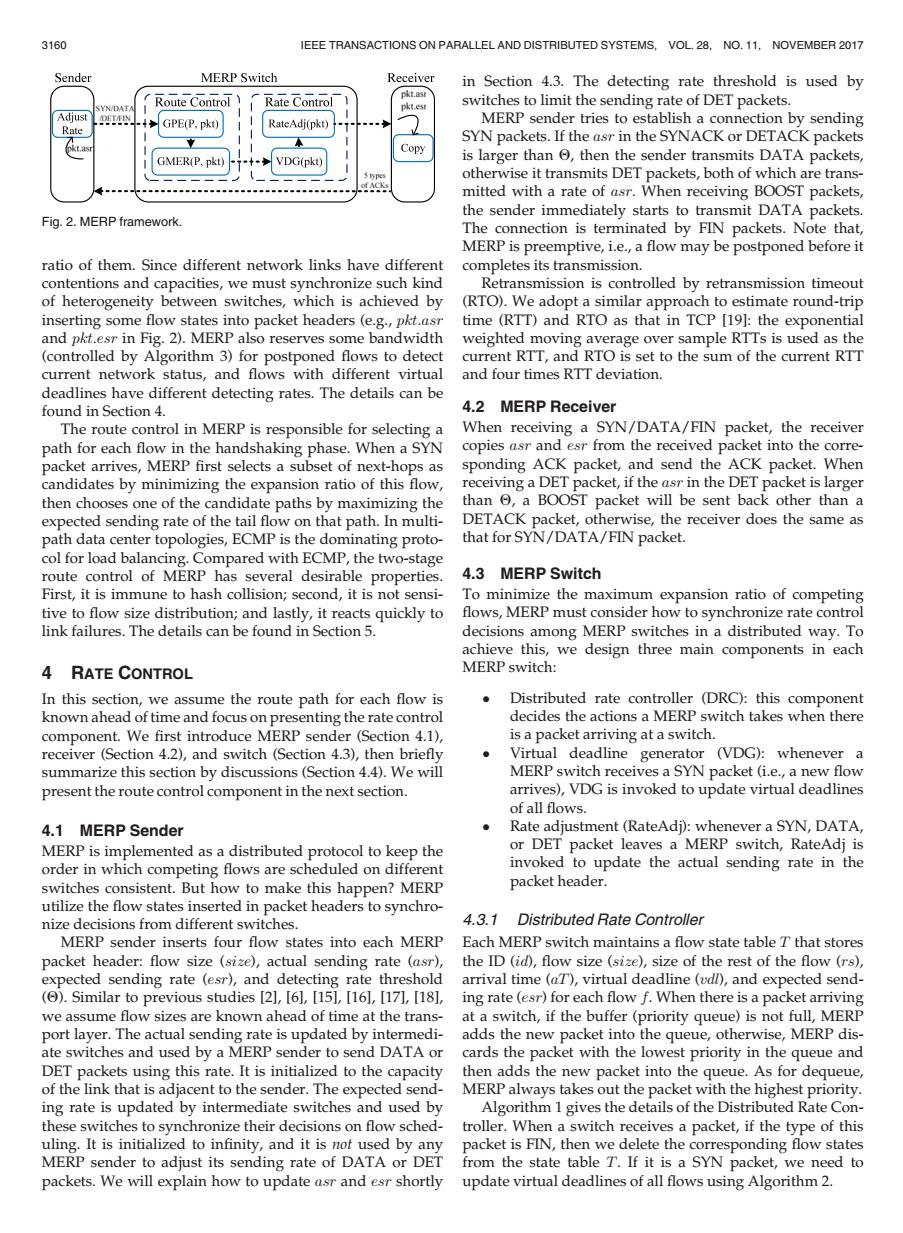
3160 IEEE TRANSACTIONS ON PARALLEL AND DISTRIBUTED SYSTEMS,VOL 28,NO.11.NOVEMBER 2017 Sender MERP Switch Receiver in Section 4.3.The detecting rate threshold is used by pkt.ast Route Control Rate Control pkt.es switches to limit the sending rate of DET packets. Adjust GPE(P.pkt) RateAdj(pkt) MERP sender tries to establish a connection by sending Rate SYN packets.If the asr in the SYNACK or DETACK packets pkt.a Copy GMER(P,pkt VDG(pkt) is larger than then the sender transmits DATA packets, otherwise it transmits DET packets,both of which are trans- mitted with a rate of asr.When receiving BOOST packets, the sender immediately starts to transmit DATA packets. Fig.2.MERP framework. The connection is terminated by FIN packets.Note that, MERP is preemptive,i.e.,a flow may be postponed before it ratio of them.Since different network links have different completes its transmission. contentions and capacities,we must synchronize such kind Retransmission is controlled by retransmission timeout of heterogeneity between switches,which is achieved by (RTO).We adopt a similar approach to estimate round-trip inserting some flow states into packet headers (e.g.,pkt.asr time (RTT)and RTO as that in TCP [19]:the exponential and pkt.esr in Fig.2).MERP also reserves some bandwidth weighted moving average over sample RTTs is used as the (controlled by Algorithm 3)for postponed flows to detect current RTT,and RTO is set to the sum of the current RTT current network status,and flows with different virtual and four times RTT deviation. deadlines have different detecting rates.The details can be found in Section 4. 4.2 MERP Receiver The route control in MERP is responsible for selecting a When receiving a SYN/DATA/FIN packet,the receiver path for each flow in the handshaking phase.When a SYN copies asr and esr from the received packet into the corre- packet arrives,MERP first selects a subset of next-hops as sponding ACK packet,and send the ACK packet.When candidates by minimizing the expansion ratio of this flow, receiving a DET packet,if the asr in the DET packet is larger then chooses one of the candidate paths by maximizing the than 6,a BOOST packet will be sent back other than a expected sending rate of the tail flow on that path.In multi- DETACK packet,otherwise,the receiver does the same as path data center topologies,ECMP is the dominating proto- that for SYN/DATA/FIN packet. col for load balancing.Compared with ECMP,the two-stage route control of MERP has several desirable properties. 4.3 MERP Switch First,it is immune to hash collision;second,it is not sensi- To minimize the maximum expansion ratio of competing tive to flow size distribution;and lastly,it reacts quickly to flows,MERP must consider how to synchronize rate control link failures.The details can be found in Section 5. decisions among MERP switches in a distributed way.To achieve this,we design three main components in each 4 RATE CONTROL MERP switch: In this section,we assume the route path for each flow is Distributed rate controller (DRC):this component known ahead of time and focus on presenting the rate control decides the actions a MERP switch takes when there component.We first introduce MERP sender(Section 4.1), is a packet arriving at a switch. receiver (Section 4.2),and switch (Section 4.3),then briefly ● Virtual deadline generator (VDG):whenever a summarize this section by discussions (Section 4.4).We will MERP switch receives a SYN packet (i.e.,a new flow present the route control component in the next section. arrives),VDG is invoked to update virtual deadlines of all flows. 4.1 MERP Sender Rate adjustment(RateAdi):whenever a SYN,DATA, MERP is implemented as a distributed protocol to keep the or DET packet leaves a MERP switch,RateAdj is order in which competing flows are scheduled on different invoked to update the actual sending rate in the switches consistent.But how to make this happen?MERP packet header. utilize the flow states inserted in packet headers to synchro- nize decisions from different switches. 4.3.1 Distributed Rate Controller MERP sender inserts four flow states into each MERP Each MERP switch maintains a flow state table T that stores packet header:flow size(size),actual sending rate (asr), the ID (id),flow size (size),size of the rest of the flow (rs), expected sending rate (esr),and detecting rate threshold arrival time (aT),virtual deadline (udl),and expected send- ()Similar to previous studies [2],[61,[15],[16],[17],[18], ing rate (esr)for each flow f.When there is a packet arriving we assume flow sizes are known ahead of time at the trans- at a switch,if the buffer(priority queue)is not full,MERP port layer.The actual sending rate is updated by intermedi- adds the new packet into the queue,otherwise,MERP dis- ate switches and used by a MERP sender to send DATA or cards the packet with the lowest priority in the queue and DET packets using this rate.It is initialized to the capacity then adds the new packet into the queue.As for dequeue, of the link that is adjacent to the sender.The expected send-MERP always takes out the packet with the highest priority. ing rate is updated by intermediate switches and used by Algorithm 1 gives the details of the Distributed Rate Con- these switches to synchronize their decisions on flow sched-troller.When a switch receives a packet,if the type of this uling.It is initialized to infinity,and it is nof used by any packet is FIN,then we delete the corresponding flow states MERP sender to adjust its sending rate of DATA or DET from the state table T.If it is a SYN packet,we need to packets.We will explain how to update asr and esr shortly update virtual deadlines of all flows using Algorithm 2.ratio of them. Since different network links have different contentions and capacities, we must synchronize such kind of heterogeneity between switches, which is achieved by inserting some flow states into packet headers (e.g., pkt:asr and pkt:esr in Fig. 2). MERP also reserves some bandwidth (controlled by Algorithm 3) for postponed flows to detect current network status, and flows with different virtual deadlines have different detecting rates. The details can be found in Section 4. The route control in MERP is responsible for selecting a path for each flow in the handshaking phase. When a SYN packet arrives, MERP first selects a subset of next-hops as candidates by minimizing the expansion ratio of this flow, then chooses one of the candidate paths by maximizing the expected sending rate of the tail flow on that path. In multipath data center topologies, ECMP is the dominating protocol for load balancing. Compared with ECMP, the two-stage route control of MERP has several desirable properties. First, it is immune to hash collision; second, it is not sensitive to flow size distribution; and lastly, it reacts quickly to link failures. The details can be found in Section 5. 4 RATE CONTROL In this section, we assume the route path for each flow is known ahead of time and focus on presenting the rate control component. We first introduce MERP sender (Section 4.1), receiver (Section 4.2), and switch (Section 4.3), then briefly summarize this section by discussions (Section 4.4). We will present the route control component in the next section. 4.1 MERP Sender MERP is implemented as a distributed protocol to keep the order in which competing flows are scheduled on different switches consistent. But how to make this happen? MERP utilize the flow states inserted in packet headers to synchronize decisions from different switches. MERP sender inserts four flow states into each MERP packet header: flow size (size), actual sending rate (asr), expected sending rate (esr), and detecting rate threshold (Q). Similar to previous studies [2], [6], [15], [16], [17], [18], we assume flow sizes are known ahead of time at the transport layer. The actual sending rate is updated by intermediate switches and used by a MERP sender to send DATA or DET packets using this rate. It is initialized to the capacity of the link that is adjacent to the sender. The expected sending rate is updated by intermediate switches and used by these switches to synchronize their decisions on flow scheduling. It is initialized to infinity, and it is not used by any MERP sender to adjust its sending rate of DATA or DET packets. We will explain how to update asr and esr shortly in Section 4.3. The detecting rate threshold is used by switches to limit the sending rate of DET packets. MERP sender tries to establish a connection by sending SYN packets. If the asr in the SYNACK or DETACK packets is larger than Q, then the sender transmits DATA packets, otherwise it transmits DET packets, both of which are transmitted with a rate of asr. When receiving BOOST packets, the sender immediately starts to transmit DATA packets. The connection is terminated by FIN packets. Note that, MERP is preemptive, i.e., a flow may be postponed before it completes its transmission. Retransmission is controlled by retransmission timeout (RTO). We adopt a similar approach to estimate round-trip time (RTT) and RTO as that in TCP [19]: the exponential weighted moving average over sample RTTs is used as the current RTT, and RTO is set to the sum of the current RTT and four times RTT deviation. 4.2 MERP Receiver When receiving a SYN/DATA/FIN packet, the receiver copies asr and esr from the received packet into the corresponding ACK packet, and send the ACK packet. When receiving a DET packet, if the asr in the DET packet is larger than Q, a BOOST packet will be sent back other than a DETACK packet, otherwise, the receiver does the same as that for SYN/DATA/FIN packet. 4.3 MERP Switch To minimize the maximum expansion ratio of competing flows, MERP must consider how to synchronize rate control decisions among MERP switches in a distributed way. To achieve this, we design three main components in each MERP switch: Distributed rate controller (DRC): this component decides the actions a MERP switch takes when there is a packet arriving at a switch. Virtual deadline generator (VDG): whenever a MERP switch receives a SYN packet (i.e., a new flow arrives), VDG is invoked to update virtual deadlines of all flows. Rate adjustment (RateAdj): whenever a SYN, DATA, or DET packet leaves a MERP switch, RateAdj is invoked to update the actual sending rate in the packet header. 4.3.1 Distributed Rate Controller Each MERP switch maintains a flow state table T that stores the ID (id), flow size (size), size of the rest of the flow (rs), arrival time (aT), virtual deadline (vdl), and expected sending rate (esr) for each flow f. When there is a packet arriving at a switch, if the buffer (priority queue) is not full, MERP adds the new packet into the queue, otherwise, MERP discards the packet with the lowest priority in the queue and then adds the new packet into the queue. As for dequeue, MERP always takes out the packet with the highest priority. Algorithm 1 gives the details of the Distributed Rate Controller. When a switch receives a packet, if the type of this packet is FIN, then we delete the corresponding flow states from the state table T. If it is a SYN packet, we need to update virtual deadlines of all flows using Algorithm 2. Fig. 2. MERP framework. 3160 IEEE TRANSACTIONS ON PARALLEL AND DISTRIBUTED SYSTEMS, VOL. 28, NO. 11, NOVEMBER 2017