正在加载图片...

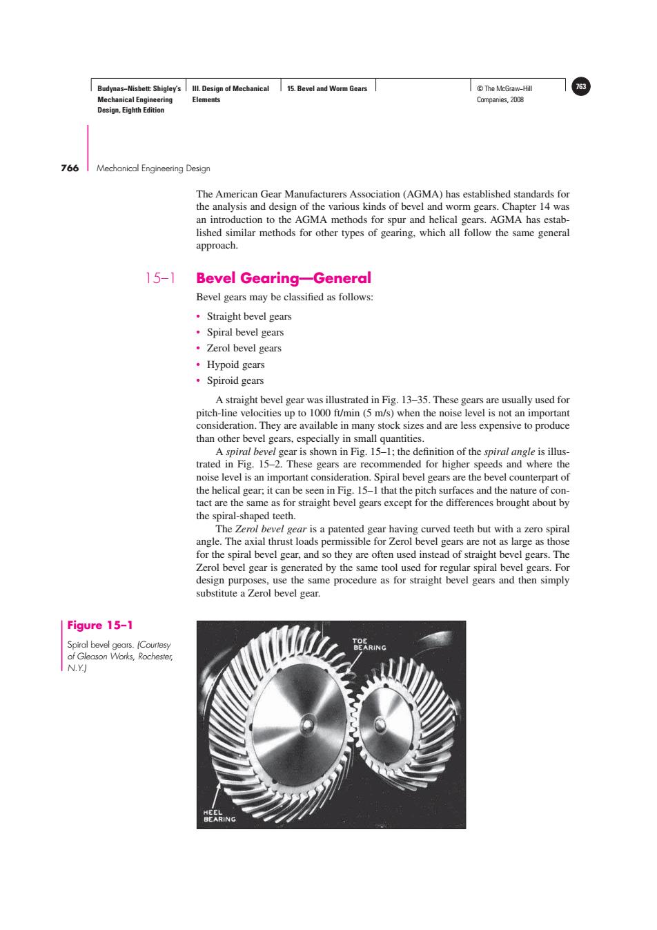
Budynas-Nisbett:Shigley's Ill.Design of Mechanical 15.Bevel and Worm Gears ©The McGraw-Hil 753 Mechanical Engineering Elements Companies,2008 Design,Eighth Edition 766 Mechanical Engineering Design The American Gear Manufacturers Association (AGMA)has established standards for the analysis and design of the various kinds of bevel and worm gears.Chapter 14 was an introduction to the AGMA methods for spur and helical gears.AGMA has estab- lished similar methods for other types of gearing,which all follow the same general approach. 15-1 Bevel Gearing-General Bevel gears may be classified as follows: ·Straight bevel gears ·Spiral bevel gears ·Zerol bevel gears ·Hypoid gears ·Spiroid gears A straight bevel gear was illustrated in Fig.13-35.These gears are usually used for pitch-line velocities up to 1000 ft/min(5 m/s)when the noise level is not an important consideration.They are available in many stock sizes and are less expensive to produce than other bevel gears,especially in small quantities. A spiral bevel gear is shown in Fig.15-1;the definition of the spiral angle is illus- trated in Fig.15-2.These gears are recommended for higher speeds and where the noise level is an important consideration.Spiral bevel gears are the bevel counterpart of the helical gear;it can be seen in Fig.15-1 that the pitch surfaces and the nature of con- tact are the same as for straight bevel gears except for the differences brought about by the spiral-shaped teeth. The Zerol bevel gear is a patented gear having curved teeth but with a zero spiral angle.The axial thrust loads permissible for Zerol bevel gears are not as large as those for the spiral bevel gear,and so they are often used instead of straight bevel gears.The Zerol bevel gear is generated by the same tool used for regular spiral bevel gears.For design purposes,use the same procedure as for straight bevel gears and then simply substitute a Zerol bevel gear. Figure 15-1 Spiral bevel gears.(Courtesy of Gleason Works,Rochester N.Y)Budynas−Nisbett: Shigley’s Mechanical Engineering Design, Eighth Edition III. Design of Mechanical Elements 15. Bevel and Worm Gears © The McGraw−Hill 763 Companies, 2008 766 Mechanical Engineering Design The American Gear Manufacturers Association (AGMA) has established standards for the analysis and design of the various kinds of bevel and worm gears. Chapter 14 was an introduction to the AGMA methods for spur and helical gears. AGMA has established similar methods for other types of gearing, which all follow the same general approach. 15–1 Bevel Gearing—General Bevel gears may be classified as follows: • Straight bevel gears • Spiral bevel gears • Zerol bevel gears • Hypoid gears • Spiroid gears A straight bevel gear was illustrated in Fig. 13–35. These gears are usually used for pitch-line velocities up to 1000 ft/min (5 m/s) when the noise level is not an important consideration. They are available in many stock sizes and are less expensive to produce than other bevel gears, especially in small quantities. A spiral bevel gear is shown in Fig. 15–1; the definition of the spiral angle is illustrated in Fig. 15–2. These gears are recommended for higher speeds and where the noise level is an important consideration. Spiral bevel gears are the bevel counterpart of the helical gear; it can be seen in Fig. 15–1 that the pitch surfaces and the nature of contact are the same as for straight bevel gears except for the differences brought about by the spiral-shaped teeth. The Zerol bevel gear is a patented gear having curved teeth but with a zero spiral angle. The axial thrust loads permissible for Zerol bevel gears are not as large as those for the spiral bevel gear, and so they are often used instead of straight bevel gears. The Zerol bevel gear is generated by the same tool used for regular spiral bevel gears. For design purposes, use the same procedure as for straight bevel gears and then simply substitute a Zerol bevel gear. Figure 15–1 Spiral bevel gears. (Courtesy of Gleason Works, Rochester, N.Y.)