正在加载图片...
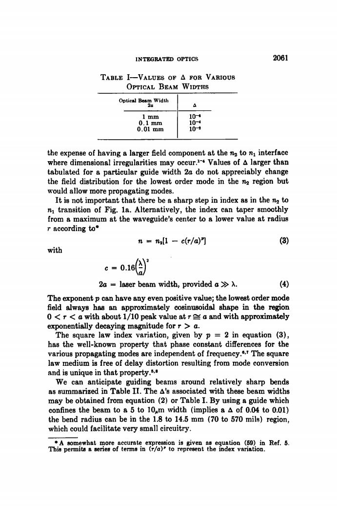
INTEGRATED OPTICS 2061 TABLE I-VALUES OF A FOR VARIOUS OPTICAL BEAM WIDTHS Optical Beam Width 2a A 1 mm 104 0.1mm 10 0.01mm 104 the expense of having a larger field component at the nz to n interface where dimensional irregularities may occur.Values of A larger than tabulated for a particular guide width 2a do not appreciably change the field distribution for the lowest order mode in the n region but would allow more propagating modes. It is not important that there be a sharp step in index as in the na to n transition of Fig.1a.Alternatively,the index can taper smoothly from a maximum at the waveguide's center to a lower value at radius r according to* n nall -c(r/a)"] (3) with c=0.16 a 2a laser beam width,provided a >A. (4) The exponent p can have any even positive value;the lowest order mode field always has an approximately cosinusoidal shape in the region 0<r<a with about 1/10 peak value at ra and with approximately exponentially decaying magnitude for r a. The square law index variation,given by p =2 in equation (3), has the well-known property that phase constant differences for the various propagating modes are independent of frequency..The square law medium is free of delay distortion resulting from mode conversion and is unique in that property.s. We can anticipate guiding beams around relatively sharp bends as summarized in Table II.The A's associated with these beam widths may be obtained from equation(2)or Table I.By using a guide which confines the beam to a 5 to 10m width (implies aA of 0.04 to 0.01) the bend radius can be in the 1.8 to 14.5 mm (70 to 570 mils)region, which could facilitate very small circuitry. *A somewhat more accurate expression is given as equation (59)in Ref.5. This permita a series of terms in(r/a)'to represent the index variation.INTEGRATED OPTICS 2061 Optical Beam Width 2a Δ I m m 10-· 0 . 1 m m lOr* 0.0 1 m m 10-« the expense of having a larger field component a t the to Πι interface where dimensional irregularities may occur.*'* Values of Δ larger than tabulated for a particular guide width 2a do not appreciably change the field distribution for the lowest order mode in the n-i region but would allow more propagating modes. It is not important tha t there be a sharp step in index as in the to Πι transition of Fig. la . Alternatively, the index can taper smoothly from a maximum a t the waveguide's center to a lower value a t radius r according to* η = n,[l - c(r/a)n (3) with c = o.ief-V 2a = laser beam width, provided o » λ. (4) The exponent ρ can have any even positive value; the lowest order mode field always has an approximately cosinusoidal shape in the region 0 < r < o with about 1/10 peak value a t r ^ o and with approximately exponentially decaying magnitude for r > a. The square law index variation, given by ρ = 2 in equation (3), has the well-known property tha t phase constant differences for the various propagating modes are independent of frequency.*-' The square law medium is free of delay distortion resulting from mode conversion and is unique in tha t property."-* We can anticipate guiding beams around relatively sharp bends as summarized in Table II. The Δ's associated with these beam widths may be obtained from equation (2) or Table I. By using a guide which confines the beam to a 5 to lO^m width (implies a Δ of 0.04 to 0.01) the bend radius can be in the 1.8 to 14.5 mm (70 to 570 mils) region, which could facilitate very small circuitry. * A somewhat more accurate expression is given as equation (50) in Ref. 5. This permits a series of terms in (r/a)' to represent the index variation. TABLE I—VALUES OF Δ FOR VARIOUS OPTICAL BEAM WIDTHS