正在加载图片...

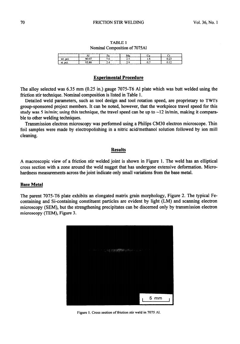
70 FRICTION STIR WELDING Vol.36,No.I TABLE I Nominal Composition of 7075Al Mg wt.pcl. 007 0.23 93 2.4 29 07 0.12 Experimental Procedure The alloy selected was 6.35 mm(0.25 in.)gauge 7075-T6 Al plate which was butt welded using the friction stir technique.Nominal composition is listed in Table 1. Detailed weld parameters,such as tool design and tool rotation speed,are proprietary to TWI's group-sponsored project members.It can be noted,however,that the workpiece travel speed for this study was 5 in/min;using this technique,the travel speed can be up to~12 in/min,making it compara- ble to other welding techniques. Transmission electron microscopy was performed using a Philips CM30 electron microscope.Thin foil samples were made by electropolishing in a nitric acid/methanol solution followed by ion mill cleaning. Results A macroscopic view of a friction stir welded joint is shown in Figure 1.The weld has an elliptical cross section with a zone around the weld nugget that has undergone extensive deformation.Micro- hardness measurements across the joint indicate only small variations from the base metal. Base Metal The parent 7075-T6 plate exhibits an elongated matrix grain morphology,Figure 2.The typical Fe- containing and Si-containing constituent particles are evident by light (LM)and scanning electron microscopy(SEM),but the strengthening precipitates can be discerned only by transmission electron microscopy(TEM),Figure 3. 5 mm Figure 1.Cross section of friction stir weld in 7075 Al.70 FRICTION STIR WELDING Vol. 36, No. 1 TABLE 1 Nominal Composition of 7075Al ( Al I %n I hlg I cu I yoo7 I 56 1 2.5 I I.6 ‘J3.M 2.4 I 2.9 I 0.7 I Cr I 0.23 I nt2 Experimental Procedure The alloy selected was 6.35 mm (0.25 in.) gauge 7075T6 Al plate which was butt welded using the friction stir technique. Nominal composition is listed in Table 1. Detailed weld parameters, such as tool design and tool rotation speed, are proprietary to TWI’s group-sponsored project members. It can be noted, however, that the workpiece travel speed for this study was 5 in/min; using this technique, the travel speed can be up to -12 in/mm making it comparable to other welding techniques. Transmission electron microscopy was performed using a Philips CM30 electron microscope. Thin foil samples were made by electropolishing in a nitric acid/methanol solution followed by ion mill cleaning. Results A macroscopic view of a friction stir welded joint is shown in Figure 1. The weld has an elliptical cross section with a zone around the weld nugget that has undergone extensive deformation. Microhardness measurements across the joint indicate only small variations from the base metal. Base Metal The parent 7075-T6 plate exhibits an elongated matrix grain morphology, Figure 2. The typical Fecontaining and Si-containing constituent particles are evident by light (LM) and scanning electron microscopy (SEM), but the strengthening precipitates can be discerned only by transmission electron microscopy (TEM), Figure 3. Figure 1. Cross section of friction stir weld in 7075 Al