正在加载图片...
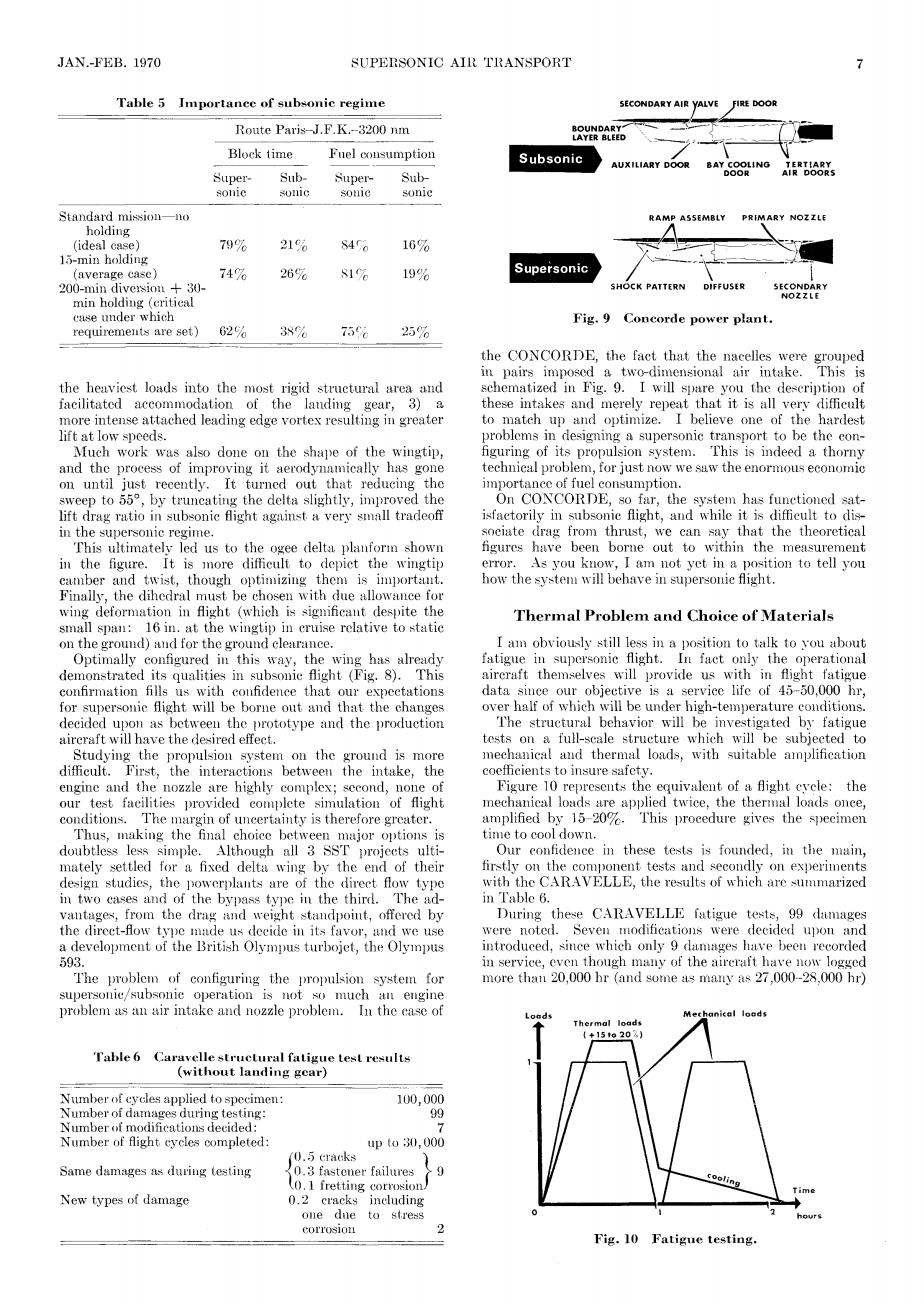
JAN.-FEB.1970 SUPERSONIC AIR TRANSPORT 7 Table 5 Importance of subsonic regime SECONDARY AIR YALVE FIRE DOOR Route Paris-J.F.K.-3200 nm LAVER Block time Fnel consumption Subsonic AUXILIARY DOOR BAY COOLING Super- Sub- Super- Sub- DOOR sonic sonic sonie sonic Standard mission—lo RAMP ASSEMBLY PRIMARY NOZZLE holding (ideal case) 79% 21% 840 16% 15-min holding (average case) 74% 267% S1% 19% Supersonic 200-min diversion 30- SHOCK PATTERN FUSER NOZZLE min holding (eritical case under which Fig.9 Concorde power plant. requirements are set) 62% 38% 75元 25% the CONCORDE,the fact that the nacelles were grouped in pairs imposed a two-dimensional air intake.This is the heaviest loads into the most rigid structural area and schematized in Fig.9.I will spare you the deseription of facilitated accommodation of the landing gear,3)a these intakes and merely repeat that it is all very difficult more intense attached leading edge vortex resulting in greater to match up and optimize.I believe one of the hardest lift at low speeds. problems in designing a supersonic transport to be the con- Much work was also done on the shape of the wingtip, figuring of its propulsion system.This is indeed a thorny and the process of improving it aerodynamically has gone technical problem,for just now we saw the enormous economie on until just recently.It turned out that reducing the importance of fuel consumption. sweep to 559,by truncating the delta slightly,improved the On CONCORDE,so far,the system has functioned sat- lift drag ratio in subsonic flight against a very small tradeoff isfactorily in subsonic flight,and while it is difficult to dis- in the supersonic regime. sociate drag from thrust,we can say that the theoretical This ultimately led us to the ogee delta planfori shown figures have been borne out to within the measurement in the figure.It is more difficult to depict the wingtip error. As you know,I am not yet in a position to tell you camber and twist,though optimizing them is importaut. how the system will behave in supersonie flight. Finally,the dihedral must be chosen with due allowance for wing deformation in flight (which is significant despite the Thermal Problem and Choice of Materials small span:16 in.at the wingtip in cruise relative to static on the ground)and for the ground clearance. I am obviously still less in a position to talk to you about Optimally configured in this way,the wing has already fatigue in supersonic flight.In fact only the operational demonstrated its qualities in subsonie flight (Fig.8).This aircraft themselves will provide us with in flight fatigue confirmation fills us with confidence that our expectations data since our objective is a service life of 45-50,000 hr. for supersonic flight will be borne out and that the changes over half of which will be under high-temperature conditions. decided upon as between the prototype and the production The structural behavior will be investigated by fatigue aireraft will have the desired effect. tests on a full-scale structure which will be subjeeted to Studying the propulsion system on the ground is more mechanical and thermal loads,with suitable amplification difficult.First,the interactions between the intake,the coefficients to insure safety. engine and the nozzle are highly complex;second,none of Figure 10 represents the equivalent of a flight eyele:the our test facilities provided complete simulation of flight mechanical loads are applied twice,the thermal loads once, conditions.The margin of uncertainty is therefore greater. amplified by 15-20%.This procedure gives the speeimen Thus,making the final choice between major options is time to cool down. doubtless less simple.Although all 3 SST projects ulti- Our confidence in these tests is founded,in the main, mately settled for a fixed delta wing by the end of their firstly on the component tests and secondly on experiments design studies,the powerplants are of the direct flow type with the CARAVELLE,the results of which are summarized in two cases and of the bypass type in the third.The ad- in Table 6. vautages,from the drag and weight standpoint,offered by During these CARAVELLE fatigue tests,99 damages the direct-flow type made us decide in its favor,and we use were noted.Seven modifications were decided upon and a development of the British Olympus turbojet,the Olympus introduced,since which only 9 damages have been recorded 593. in service,even though many of the aireraft have now logged The problem of configuring the propulsion system for more than 20,000 hr (and some as many as 27,000-28,000 hr) supersonie/subsonic operation is not so much an engine problem as an air intake and nozzle problem.In the case of Thermal loads 1+151o202 Table 6 Caravelle structural fatigue test results (without landing gear) Number of cycles applied to specimen: 100.000 Number of damages during testing: 99 Number of modifications decided: Number of flight cycles completed: upt030,000 (0.5 cracks Same damages as during testing 0.3 fastener failures 9 (0.1 fretting corrosion New types of damage 0.2 cracks including one dne to stress corrosion Fig.10 Fatigue testing.JAN.-FEB. 1970 SUPERSONIC AIR TRANSPORT Table 5 Importance of subsonic regime SECONDARY AIR VALVE Route Paris-J.F.K.-3200 nm Fuel consumption SubBlock time Super- Sub- Supersonic sonic sonic sonic Standard mission—no holding (ideal case) 79% 15-min holding (average case) 74% 200-min diversion -f 30- min holding (critical case under which requirements are set) 62% 21% 84% 26% 81% 38% 75% 16% 19% the heaviest loads into the most rigid structural area and facilitated accommodation of the landing gear, 3) a more intense attached leading edge vortex resulting in greater lift at low speeds. Much work was also done on the shape of the wingtip, and the process of improving it aerodynamically has gone on until just recently. It turned out that reducing the sweep to 55°, by truncating the delta slightly, improved the lift drag ratio in subsonic flight against a very small tradeoff in the supersonic regime. This ultimately led us to the ogee delta planform shown in the figure. It is more difficult to depict the wingtip camber and twist, though optimizing them is important. Finally, the dihedral must be chosen with due allowance for wing deformation in flight (which is significant despite the small span: 16 in. at the wingtip in cruise relative to static on the ground) and for the ground clearance. Optimally configured in this way, the wing has already demonstrated its qualities in subsonic flight (Fig. 8). This confirmation fills us with confidence that our expectations for supersonic flight will be borne out and that the changes decided upon as between the prototype and the production aircraft will have the desired effect. Studying the propulsion system on the ground is more difficult. First, the interactions between the intake, the engine and the nozzle are highly complex; second, none of our test facilities provided complete simulation of flight conditions. The margin of uncertainty is therefore greater. Thus, making the final choice between major options is doubtless less simple. Although all 3 SST projects ultimately settled for a fixed delta wing by the end of their design studies, the powerplants are of the direct flow type in two cases and of the bypass type in the third. The advantages, from the drag and weight standpoint, offered by the direct-flow type made us decide in its favor, and we use a development of the British Olympus turbojet, the Olympus 593. The problem of configuring the propulsion system for supersonic/subsonic operation is not so much an engine problem as an air intake and nozzle problem. In the case of Table 6 Caravelle structural fatigue test results (without landing gear) Number of cycles applied to specimen: Number of damages during testing: Number of modifications decided: Number of flight cycles completed: Same damages as during testing New types of damage 100,000 99 7 up to 30,000 0.5 cracks "} 0.3 fastener failures /• 9 0.1 fretting corrosion/ 0.2 cracks including one due to stress corrosion 2 BOUNDARY^ LAYER BLEED Subsonic AUXILIARY DOOR BAY COOLING DOOR TERTIARY AIR DOORS RAMP ASSEMBLY PRIMARY NOZZLE A_____\ Supersonic SHOCK PATTERN DIFFUSER SECONDARY NOZZLE Fig. 9 Concorde power plant. the CONCORDE, the fact that the nacelles were grouped in pairs imposed a two-dimensional air intake. This is schematized in Fig. 9. I will spare you the description of these intakes and merely repeat that it is all very difficult to match up and optimize. I believe one of the hardest problems in designing a supersonic transport to be the configuring of its propulsion system. This is indeed a thorny technical problem, for just now we saw the enormous economic importance of fuel consumption. On CONCORDE, so far, the system has functioned satisfactorily in subsonic flight, and while it is difficult to dissociate drag from thrust, we can say that the theoretical figures have been borne out to within the measurement error. As you know, I am not yet in a position to tell you how the system will behave in supersonic flight. Thermal Problem and Choice of Materials I am obviously still less in a position to talk to you about fatigue in supersonic flight. In fact only the operational aircraft themselves will provide us with in flight fatigue data since our objective is a service life of 45-50,000 hr, over half of which will be under high-temperature conditions. The structural behavior will be investigated by fatigue tests on a full-scale structure which will be subjected to mechanical and thermal loads, with suitable amplification coefficients to insure safety. Figure 10 represents the equivalent of a flight cycle: the mechanical loads are applied twice, the thermal loads once, amplified by 15-20%. This procedure gives the specimen time to cool down. Our confidence in these tests is founded, in the main, firstly on the component tests and secondly on experiments with the CARAVELLE, the results of which are summarized in Table 6. During these CARAVELLE fatigue tests, 99 damages were noted. Seven modifications were decided upon and introduced, since which only 9 damages have been recorded in service, even though many of the aircraft have now logged more than 20,000 hr (and some as many as 27,000-28,000 hr) Fig. 10 Fatigue testing