正在加载图片...
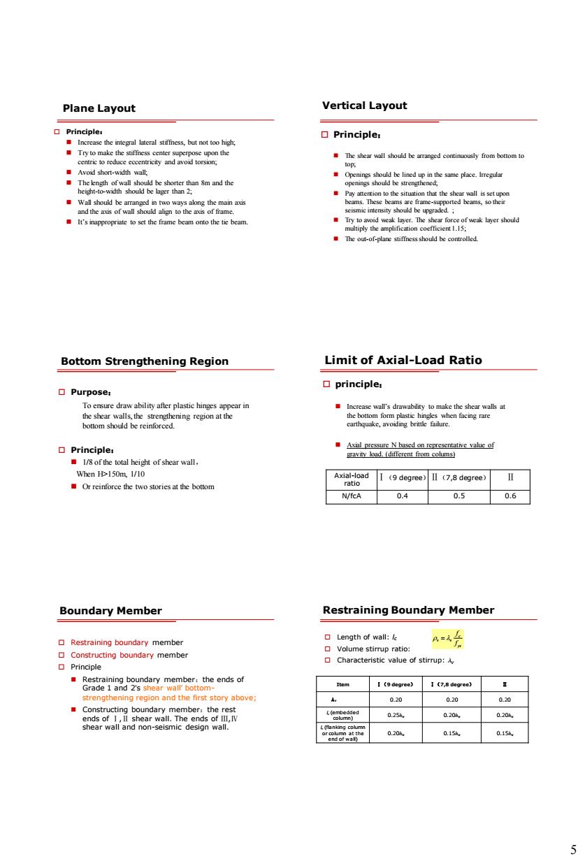
Plane Layout Vertical Layout T kymdedanaome · Bottom Strengthening Region Limit of Axial-Load Ratio 口Purpose principle, When 150m.1/10 I(degree)Il (7,degree)l WkcA0.40.50.6 Boundary Member Restraining Boundary Membe 口ength of wall:k Restraining boundary membe member ·&61a2x2m8 no0 0.20 0.20 0.20 025 mn at the5 Plane Layout Principle: Increase the integral lateral stiffness, but not too high; Try to make the stiffness center superpose upon the centric to reduce eccentricity and avoid torsion; Avoid short-width wall; The length of wall should be shorter than 8m and the height-to-width should be lager than 2; Wall should be arranged in two ways along the main axis and the axis of wall should align to the axis of frame. It’s inappropriate to set the frame beam onto the tie beam. Vertical Layout Principle: The shear wall should be arranged continuously from bottom to top; Openings should be lined up in the same place. Irregular openings should be strengthened; Pay attention to the situation that the shear wall is set upon beams. These beams are frame-supported beams, so their seismic intensity should be upgraded. ; Try to avoid weak layer. The shear force of weak layer should multiply the amplification coefficient 1.15; The out-of-plane stiffness should be controlled. Bottom Strengthening Region Purpose: To ensure draw ability after plastic hinges appear in the shear walls, the strengthening region at the bottom should be reinforced. Principle: 1/8 of the total height of shear wall, When H>150m, 1/10 Or reinforce the two stories at the bottom Limit of Axial-Load Ratio principle: Increase wall’s drawability to make the shear walls at the bottom form plastic hingles when facing rare earthquake, avoiding brittle failure. Axial pressure N based on representative value of gravity load. (different from colums) Axial-load ratio Ⅰ(9 degree)Ⅱ(7,8 degree) Ⅱ N/fcA 0.4 0.5 0.6 Boundary Member Restraining boundary member Constructing boundary member Principle Restraining boundary member:the ends of Grade 1 and 2’s shear wall’ bottomstrengthening region and the first story above; Constructing boundary member:the rest ends of Ⅰ,Ⅱ shear wall. The ends of Ⅲ,Ⅳ shear wall and non-seismic design wall. Restraining Boundary Member Length of wall: lc Volume stirrup ratio: Characteristic value of stirrup: v Item Ⅰ(9 degree) Ⅰ(7,8 degree) Ⅱ v 0.20 0.20 0.20 lc (embedded column) 0.25hw 0.20hw 0.20hw lc (flanking column or column at the end of wall) 0.20hw 0.15hw 0.15hw c v v yv f f