正在加载图片...
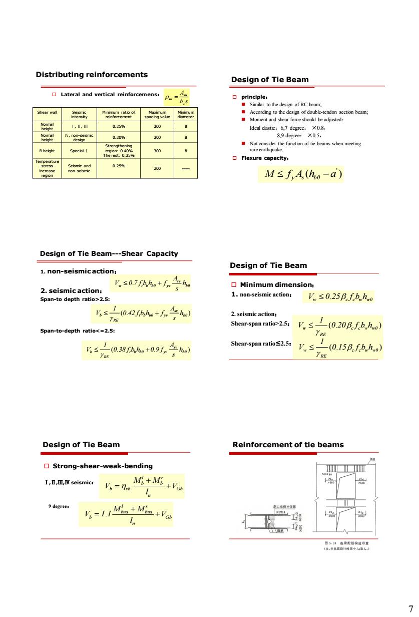
Distributing reinforcements Design of Tie Beam Lateral and vertical reinforcemens. hould 100 025% M≤fA,(ho-a) Design of Tie Beam---Shear Capacity 1.non-seismicaction: Design of Tie Beam Ks0.7fho+人nw V≤0.25Bfhh s名0Pe+人子w 2.seismis action Span-to-depth ratio<=2.5: Shear-span ratio>2.5: 1(0.20B.f.b.h.o 5≤名a8AM+09.女w Shear-span ratio2.5.≤(0.15.fhh.o YRE Design of Tie Beam Reinforcement of tie beams Strong-shear-weak-bending 1,,M,seismic 5=+证+a =1a+M@+27 Distributing reinforcements Lateral and vertical reinforcemens: sw sw w A b s Shear wall Seismic intensity Minimum ratio of reinforcement Maximum spacing value Minimum diameter Normal height Ⅰ, Ⅱ, Ⅲ 0.25% 300 8 Normal height Ⅳ, non-seismic design 0.20% 300 8 B height Special Ⅰ Strengthening region: 0.40% The rest: 0.35% 300 8 Temperature -stressincrease region Seismic and non-seismic 0.25% 200 —— Design of Tie Beam principle: Similar to the design of RC beam; According to the design of double-tendon section beam; Moment and shear force should be adjusted: Ideal elastic:6,7 degree: ×0.8, 8,9 degree: ×0.5, Not consider the function of tie beams when meeting rare earthquake. Flexure capacity: ' ( ) M f A h a y s b0 1. non-seismic action: 2. seismic action: Span-to depth ratio>2.5: Span-to-depth ratio<=2.5: . sv w t b b0 yv b0 A V 0 7 f b h f h s ( . ) sv b t b b0 yv b0 RE 1 A V 0 42 f b h f h s ( . . ) sv b t b b0 yv b0 RE 1 A V 0 38 f b h 0 9 f h s Design of Tie Beam---Shear Capacity Minimum dimension: 1. non-seismic action: 2. seismic action: Shear-span ratio>2.5: Shear-span ratio≤2.5: . V 0 25 f b h w c c w w0 ( . ) w c c w w0 RE 1 V 0 20 f b h ( . ) w c c w w0 RE 1 V 0 15 f b h Design of Tie Beam Strong-shear-weak-bending Ⅰ,Ⅱ,Ⅲ,Ⅳ seismic: 9 degree: l r b b b vb Gb n M M V V l . l r bua bua b Gb n M M V 1 1 V l Design of Tie Beam Reinforcement of tie beams