正在加载图片...
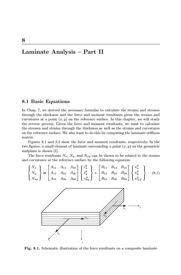
8 Laminate Analysis -Part II 8.1 Basic Equations In Chap.7,we derived the necessary formulas to calculate the strains and stresses through the thickness and the force and moment resultants given the strains and curvatures at a point (r,y)on the reference surface.In this chapter,we will study the reverse process.Given the force and moment resultants,we want to calculate the stresses and strains through the thickness as well as the strains and curvatures on the reference surface.We also want to do this by computing the laminate stiffness matrix. Figures 8.1 and 8.2 show the force and moment resultants,respectively.In the two figures,a small element of laminate surrounding a point (r,y)on the geometric midplane is shown [1]. The force resultants Nr,Ny,and Ny can be shown to be related to the strains and curvatures at the reference surface by the following equation: A11 A12 A16 e [B11 B12 B16 A12 A22 0 B12 B22 B26 (8.1) A16 A26 A66」 B16B26 B66 R%Y Fig.8.1.Schematic illustration of the force resultants on a composite laminate8 Laminate Analysis – Part II 8.1 Basic Equations In Chap. 7, we derived the necessary formulas to calculate the strains and stresses through the thickness and the force and moment resultants given the strains and curvatures at a point (x, y) on the reference surface. In this chapter, we will study the reverse process. Given the force and moment resultants, we want to calculate the stresses and strains through the thickness as well as the strains and curvatures on the reference surface. We also want to do this by computing the laminate stiffness matrix. Figures 8.1 and 8.2 show the force and moment resultants, respectively. In the two figures, a small element of laminate surrounding a point (x, y) on the geometric midplane is shown [1]. The force resultants Nx, Ny, and Nxy can be shown to be related to the strains and curvatures at the reference surface by the following equation: ⎧ ⎪⎨ ⎪⎩ Nx Ny Nxy ⎫ ⎪⎬ ⎪⎭ = ⎡ ⎢ ⎣ A11 A12 A16 A12 A22 A26 A16 A26 A66 ⎤ ⎥ ⎦ ⎧ ⎪⎨ ⎪⎩ ε0 x ε0 y γ0 xy ⎫ ⎪⎬ ⎪⎭ + ⎡ ⎢ ⎣ B11 B12 B16 B12 B22 B26 B16 B26 B66 ⎤ ⎥ ⎦ ⎧ ⎪⎨ ⎪⎩ κ0 x κ0 y κ0 XY ⎫ ⎪⎬ ⎪⎭ (8.1) Fig. 8.1. Schematic illustration of the force resultants on a composite laminate