正在加载图片...
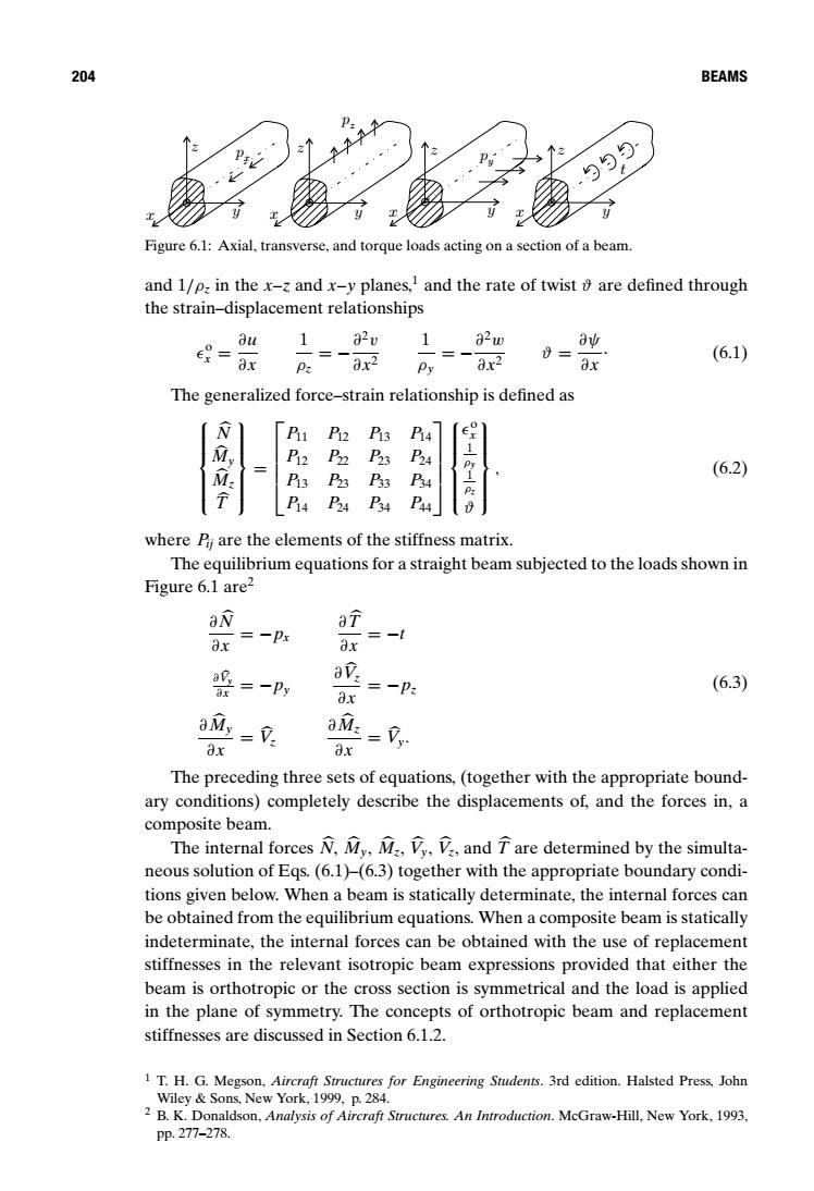
204 BEAMS 与与与 Figure 6.1:Axial,transverse,and torque loads acting on a section of a beam. and 1/p,in the x-z and x-y planes,and the rate of twist are defined through the strain-displacement relationships Bu 12v 82w a业 = ax 8x2 ax (6.1) Pz Py The generalized force-strain relationship is defined as N P P2 Pi3 P2 (6.2) Pi3 P33 4 P2A P4 where Pi are the elements of the stiffness matrix. The equilibrium equations for a straight beam subjected to the loads shown in Figure 6.1 are2 aN aT ax =一Px ax =一Py ap ax (6.3) ax =-P aMy -V: aM: = ax ax The preceding three sets of equations,(together with the appropriate bound- ary conditions)completely describe the displacements of,and the forces in,a composite beam. The internal forces N,My,M,V,V,and T are determined by the simulta- neous solution of Eqs.(6.1)-(6.3)together with the appropriate boundary condi- tions given below.When a beam is statically determinate,the internal forces can be obtained from the equilibrium equations.When a composite beam is statically indeterminate,the internal forces can be obtained with the use of replacement stiffnesses in the relevant isotropic beam expressions provided that either the beam is orthotropic or the cross section is symmetrical and the load is applied in the plane of symmetry.The concepts of orthotropic beam and replacement stiffnesses are discussed in Section 6.1.2. 1 T.H.G.Megson,Aircraft Structures for Engineering Students.3rd edition.Halsted Press,John Wiley Sons,New York,1999,p.284. 2 B.K.Donaldson,Analysis of Aircraft Structures.An Introduction.McGraw-Hill.New York.1993. Pp.277-278.204 BEAMS z x y pz z py z t x y x y z y x px Figure 6.1: Axial, transverse, and torque loads acting on a section of a beam. and 1/ρz in the x–z and x–y planes,1 and the rate of twist ϑ are defined through the strain–displacement relationships o x = ∂u ∂x 1 ρz = −∂2v ∂x2 1 ρy = −∂2w ∂x2 ϑ = ∂ψ ∂x . (6.1) The generalized force–strain relationship is defined as N My Mz T = P11 P12 P13 P14 P12 P22 P23 P24 P13 P23 P33 P34 P14 P24 P34 P44 o x 1 ρy 1 ρz ϑ , (6.2) where Pij are the elements of the stiffness matrix. The equilibrium equations for a straight beam subjected to the loads shown in Figure 6.1 are2 ∂N ∂x = −px ∂T ∂x = −t ∂V y ∂x = −py ∂V z ∂x = −pz ∂My ∂x = V z ∂Mz ∂x = V y. (6.3) The preceding three sets of equations, (together with the appropriate boundary conditions) completely describe the displacements of, and the forces in, a composite beam. The internal forces N, My, Mz, V y, V z, and T are determined by the simultaneous solution of Eqs. (6.1)–(6.3) together with the appropriate boundary conditions given below. When a beam is statically determinate, the internal forces can be obtained from the equilibrium equations. When a composite beam is statically indeterminate, the internal forces can be obtained with the use of replacement stiffnesses in the relevant isotropic beam expressions provided that either the beam is orthotropic or the cross section is symmetrical and the load is applied in the plane of symmetry. The concepts of orthotropic beam and replacement stiffnesses are discussed in Section 6.1.2. 1 T. H. G. Megson, Aircraft Structures for Engineering Students. 3rd edition. Halsted Press, John Wiley & Sons, New York, 1999, p. 284. 2 B. K. Donaldson, Analysis of Aircraft Structures. An Introduction. McGraw-Hill, New York, 1993, pp. 277–278