正在加载图片...

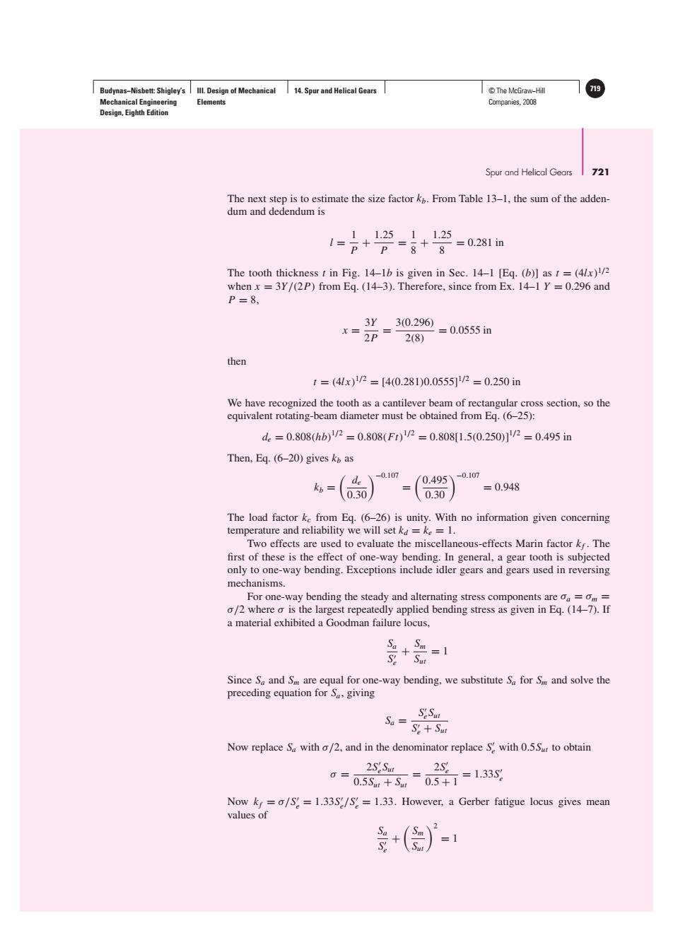
Budynas-Nisbett:Shigley's Ill.Design of Mechanical 14.Spur and Helical Gears T©The McGraw-Hill 719 Mechanical Engineering Elements Companies,2008 Design,Eighth Edition Spur and Helical Gears 721 The next step is to estimate the size factor k.From Table 13-1,the sum of the adden- dum and dedendum is 11.2511.25 1=p+P=8+8 =0.281in The tooth thickness t in Fig.14-1b is given in Sec.14-1 [Eq.(b)]ast=(4lx) when x =3Y/(2P)from Eq.(14-3).Therefore,since from Ex.14-1 Y=0.296 and P=8, 3Y3(0.296) x=2P=28) =0.0555in then t=(4lx)1/2=[4(0.281)0.0555/2=0.250in We have recognized the tooth as a cantilever beam of rectangular cross section,so the equivalent rotating-beam diameter must be obtained from Eq.(6-25): d=0.808hb)1/2=0.808(Ft)1/p=0.8081.50.250j/2=0.495in Then,Eq.(6-20)gives k as -0.107 de 0.495 、-0.107 kb=0.30/ =0.948 0.30 The load factor ke from Eq.(6-26)is unity.With no information given concerning temperature and reliability we will set k=ke=1. Two effects are used to evaluate the miscellaneous-effects Marin factor kf.The first of these is the effect of one-way bending.In general,a gear tooth is subjected only to one-way bending.Exceptions include idler gears and gears used in reversing mechanisms. For one-way bending the steady and alternating stress components are oa =om= o/2 where o is the largest repeatedly applied bending stress as given in Eq.(14-7).If a material exhibited a Goodman failure locus, + Sm=1 Since Sa and Sm are equal for one-way bending,we substitute Sa for Sm and solve the preceding equation for S,giving Sa= SeSu S+Sut Now replace S with/2,and in the denominator replace Swith 0.5S to obtain 0= =1.33S 0.5Sm+Sm0.5+1 Now k=a/S=1.33S/S?=1.33.However,a Gerber fatigue locus gives mean values of +()=1Budynas−Nisbett: Shigley’s Mechanical Engineering Design, Eighth Edition III. Design of Mechanical Elements 14. Spur and Helical Gears © The McGraw−Hill 719 Companies, 2008 Spur and Helical Gears 721 The next step is to estimate the size factor kb. From Table 13–1, the sum of the addendum and dedendum is l = 1 P + 1.25 P = 1 8 + 1.25 8 = 0.281 in The tooth thickness t in Fig. 14–1b is given in Sec. 14–1 [Eq. (b)] as t = (4lx)1/2 when x = 3Y/(2P) from Eq. (14–3). Therefore, since from Ex. 14–1 Y = 0.296 and P = 8, x = 3Y 2P = 3(0.296) 2(8) = 0.0555 in then t = (4lx) 1/2 = [4(0.281)0.0555]1/2 = 0.250 in We have recognized the tooth as a cantilever beam of rectangular cross section, so the equivalent rotating-beam diameter must be obtained from Eq. (6–25): de = 0.808(hb) 1/2 = 0.808(Ft) 1/2 = 0.808[1.5(0.250)] 1/2 = 0.495 in Then, Eq. (6–20) gives kb as kb = de 0.30−0.107 = 0.495 0.30 −0.107 = 0.948 The load factor kc from Eq. (6–26) is unity. With no information given concerning temperature and reliability we will set kd = ke = 1. Two effects are used to evaluate the miscellaneous-effects Marin factor kf . The first of these is the effect of one-way bending. In general, a gear tooth is subjected only to one-way bending. Exceptions include idler gears and gears used in reversing mechanisms. For one-way bending the steady and alternating stress components are σa = σm = σ/2 where σ is the largest repeatedly applied bending stress as given in Eq. (14–7). If a material exhibited a Goodman failure locus, Sa S e + Sm Sut = 1 Since Sa and Sm are equal for one-way bending, we substitute Sa for Sm and solve the preceding equation for Sa , giving Sa = S eSut S e + Sut Now replace Sa with σ/2, and in the denominator replace S e with 0.5Sut to obtain σ = 2S eSut 0.5Sut + Sut = 2S e 0.5 + 1 = 1.33S e Now kf = σ/S e = 1.33S e/S e = 1.33. However, a Gerber fatigue locus gives mean values of Sa S e + Sm Sut 2 = 1