正在加载图片...

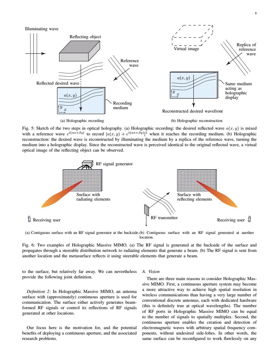
minating wave Reflecting object Virtual image Replica o wave Referenc a(r,) Reflected desired wave ing a ho a(z.y) display Recording Reconstructed desired wavefront (a)Holographic recording (b)Holographic reconstruction g.5 Sketch of theoica hologrpy.Hr the dsired refectedave)ismixed ”to record a(z when it reaches the recording medium.(b)Holographi es reconstructed by optical image of the reflecting obect can be observed. ave,2 RF signal generator 目Receiving user Re transmitter Receiving user (Coniguusrc BF sigal generaor a the backside()omiorfae Ri generad another Fig.6:Two examples of Holographic Massive MIMO.(a)The RF signal is generated at the backside of the surface and propagates through a steerable network to radiat another r location and surfacea gna a cam ()Inc Kr signal is sent elements that generate a beam provid There are three main reasons to consider Holographic Mas. Definition 2:In Holos phic Massive MIMO.an antenna active way to surface with(approximately)continuous aperture is used for conventional discrete antennas.each with dedicated hardware (this is definitely true at optical wavelengths).The numbe RF ports in MO can be equa Our focus here is the motivation for,and the potential electromagnetic waves with arbitrary spatial frequency com ponents, without undesired side-lobes words,the research problems same surface can be reconfigured to work8 Illuminating wave Reflecting object Reference wave Reflected desired wave Recording medium a(x, y) x y (a) Holographic recording Virtual image Replica of reference wave Reconstructed desired wavefront a(x, y) Same medium acting as holographic display x y (b) Holographic reconstruction Fig. 5: Sketch of the two steps in optical holography. (a) Holographic recording: the desired reflected wave a(x, y) is mixed with a reference wave e i(αx+βy) to record |a(x, y) + e i(αx+βy) | 2 when it reaches the recording medium. (b) Holographic reconstruction: the desired wave is reconstructed by illuminating the medium by a replica of the reference wave, turning the medium into a holographic display. Since the reconstructed wave is perceived identical to the original reflected wave, a virtual optical image of the reflecting object can be observed. RF signal generator Receiving user Surface with radiating elements (a) Contiguous surface with an RF signal generator at the backside. Receiving user RF transmitter Surface with reflecting elements (b) Contiguous surface with an RF signal generated at another location. Fig. 6: Two examples of Holographic Massive MIMO. (a) The RF signal is generated at the backside of the surface and propagates through a steerable distribution network to radiating elements that generate a beam. (b) The RF signal is sent from another location and the metasurface reflects it using steerable elements that generate a beam. to the surface, but relatively far away. We can nevertheless provide the following joint definition. Definition 2: In Holographic Massive MIMO, an antenna surface with (approximately) continuous aperture is used for communication. The surface either actively generates beamformed RF signals or control its reflections of RF signals generated at other locations. Our focus here is the motivation for, and the potential benefits of deploying a continuous aperture, and the associated research problems. A. Vision There are three main reasons to consider Holographic Massive MIMO. First, a continuous aperture system may become a more attractive way to achieve high spatial resolution in wireless communications than having a very large number of conventional discrete antennas, each with dedicated hardware (this is definitely true at optical wavelengths). The number of RF ports in Holographic Massive MIMO can be equal to the number of signals to spatially multiplex. Second, the continuous aperture enables the creation and detection of electromagnetic waves with arbitrary spatial frequency components, without undesired side-lobes. In other words, the same surface can be reconfigured to work flawlessly on any