正在加载图片...
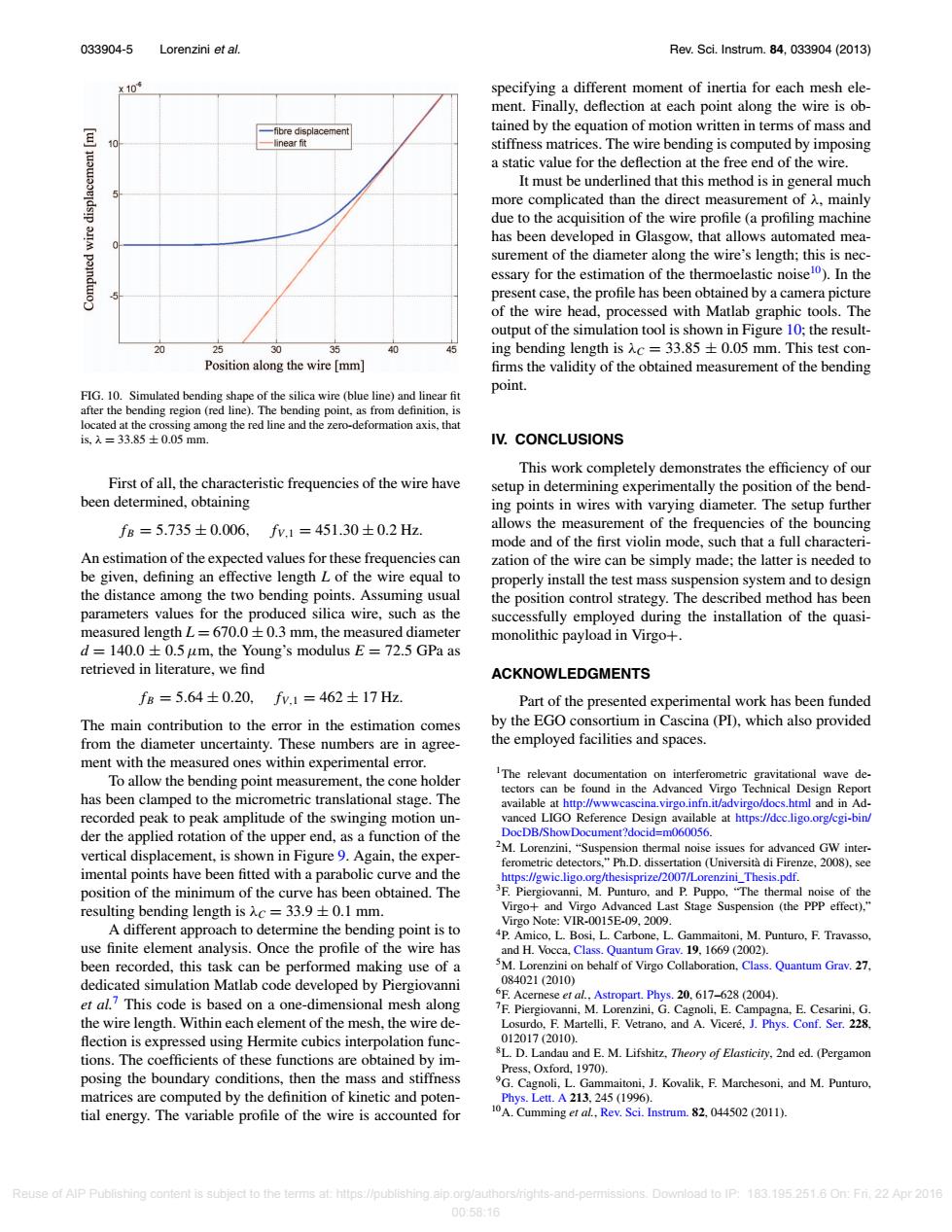
033904-5 Lorenzini et al. Rev.Sci.Instrum.84,033904(2013) x10 specifying a different moment of inertia for each mesh ele- ment.Finally,deflection at each point along the wire is ob- -fibre displacement tained by the equation of motion written in terms of mass and -linear fit stiffness matrices.The wire bending is computed by imposing a static value for the deflection at the free end of the wire. It must be underlined that this method is in general much more complicated than the direct measurement of A.mainly due to the acquisition of the wire profile(a profiling machine has been developed in Glasgow,that allows automated mea- surement of the diameter along the wire's length;this is nec- essary for the estimation of the thermoelastic noisel0).In the present case,the profile has been obtained by a camera picture of the wire head,processed with Matlab graphic tools.The output of the simulation tool is shown in Figure 10;the result- 25 30 35 40 ing bending length is Ac=33.85+0.05 mm.This test con- Position along the wire [mm] firms the validity of the obtained measurement of the bending point. FIG.10.Simulated bending shape of the silica wire (blue line)and linear fit after the bending region(red line).The bending point,as from definition,is located at the crossing among the red line and the zero-deformation axis,that is.入=33.85±0.05mm. IV.CONCLUSIONS This work completely demonstrates the efficiency of our First of all,the characteristic frequencies of the wire have setup in determining experimentally the position of the bend- been determined,obtaining ing points in wires with varying diameter.The setup further fB=5.735±0.006,fv.1=451.30±0.2Hz. allows the measurement of the frequencies of the bouncing mode and of the first violin mode,such that a full characteri- An estimation of the expected values for these frequencies can zation of the wire can be simply made;the latter is needed to be given,defining an effective length L of the wire equal to properly install the test mass suspension system and to design the distance among the two bending points.Assuming usual the position control strategy.The described method has been parameters values for the produced silica wire,such as the successfully employed during the installation of the quasi- measured length L=670.0+0.3 mm,the measured diameter monolithic payload in Virgo+. d =140.0+0.5 um,the Young's modulus E 72.5 GPa as retrieved in literature,we find ACKNOWLEDGMENTS fB=5.64±0.20,fv,1=462±17Hz. Part of the presented experimental work has been funded The main contribution to the error in the estimation comes by the EGO consortium in Cascina(PD),which also provided from the diameter uncertainty.These numbers are in agree- the employed facilities and spaces. ment with the measured ones within experimental error. To allow the bending point measurement,the cone holder IThe relevant documentation on interferometric gravitational wave de- tectors can be found in the Advanced Virgo Technical Design Report has been clamped to the micrometric translational stage.The available at http://wwwcascina.virgo.infn.it/advirgo/docs.html and in Ad- recorded peak to peak amplitude of the swinging motion un- vanced LIGO Reference Design available at https://dcc.ligo.org/cgi-bin/ der the applied rotation of the upper end,as a function of the DocDB/ShowDocument?docid=m060056. vertical displacement,is shown in Figure 9.Again,the exper- M.Lorenzini,"Suspension thermal noise issues for advanced GW inter- ferometric detectors."Ph.D.dissertation (Universita di Firenze,2008).see imental points have been fitted with a parabolic curve and the https://gwic.ligo.org/thesisprize/2007/Lorenzini_Thesis.pdf. position of the minimum of the curve has been obtained.The 3F.Piergiovanni,M.Punturo,and P.Puppo."The thermal noise of the resulting bending length is入c=33.9±0.1mm. Virgo+and Virgo Advanced Last Stage Suspension (the PPP effect).," A different approach to determine the bending point is to Virgo Note:VIR-0015E-09,2009. P.Amico,L.Bosi,L.Carbone,L.Gammaitoni,M.Punturo,F.Travasso, use finite element analysis.Once the profile of the wire has and H.Vocca.Class.Quantum Grav.19,1669 (2002). been recorded,this task can be performed making use of a 5M.Lorenzini on behalf of Virgo Collaboration,Class.Quantum Grav.27. dedicated simulation Matlab code developed by Piergiovanni 084021(2010) et al.?This code is based on a one-dimensional mesh along 6F.Acernese er al.Astropart.Phys.20.617-628(2004). 7F.Piergiovanni.M.Lorenzini,G.Cagnoli,E.Campagna,E.Cesarini,G. the wire length.Within each element of the mesh,the wire de- Losurdo,F.Martelli,F.Vetrano,and A.Vicere,J.Phys.Conf.Ser.228. flection is expressed using Hermite cubics interpolation func- 012017(2010). tions.The coefficients of these functions are obtained by im- BL.D.Landau and E.M.Lifshitz,Theory of Elasticiry,2nd ed.(Pergamon Press,Oxford,1970). posing the boundary conditions,then the mass and stiffness 9G.Cagnoli,L.Gammaitoni,J.Kovalik,F.Marchesoni,and M.Punturo, matrices are computed by the definition of kinetic and poten- Phys.Lett.A213,245(1996). tial energy.The variable profile of the wire is accounted for 10A.Cumming et al,Rev.Sci.Instrum.82.044502(2011). Reuse of AlP Publishing content is subject to the terms at:https://publishing.aip.org/authors/rights-and-permissions.Download to IP:183.195.251.6 On:Fri.22 Apr 2016 00:58:16033904-5 Lorenzini et al. Rev. Sci. Instrum. 84, 033904 (2013) FIG. 10. Simulated bending shape of the silica wire (blue line) and linear fit after the bending region (red line). The bending point, as from definition, is located at the crossing among the red line and the zero-deformation axis, that is, λ = 33.85 ± 0.05 mm. First of all, the characteristic frequencies of the wire have been determined, obtaining fB = 5.735 ± 0.006, fV,1 = 451.30 ± 0.2 Hz. An estimation of the expected values for these frequencies can be given, defining an effective length L of the wire equal to the distance among the two bending points. Assuming usual parameters values for the produced silica wire, such as the measured length L = 670.0 ± 0.3 mm, the measured diameter d = 140.0 ± 0.5μm, the Young’s modulus E = 72.5 GPa as retrieved in literature, we find fB = 5.64 ± 0.20, fV,1 = 462 ± 17 Hz. The main contribution to the error in the estimation comes from the diameter uncertainty. These numbers are in agreement with the measured ones within experimental error. To allow the bending point measurement, the cone holder has been clamped to the micrometric translational stage. The recorded peak to peak amplitude of the swinging motion under the applied rotation of the upper end, as a function of the vertical displacement, is shown in Figure 9. Again, the experimental points have been fitted with a parabolic curve and the position of the minimum of the curve has been obtained. The resulting bending length is λC = 33.9 ± 0.1 mm. A different approach to determine the bending point is to use finite element analysis. Once the profile of the wire has been recorded, this task can be performed making use of a dedicated simulation Matlab code developed by Piergiovanni et al.7 This code is based on a one-dimensional mesh along the wire length. Within each element of the mesh, the wire de- flection is expressed using Hermite cubics interpolation functions. The coefficients of these functions are obtained by imposing the boundary conditions, then the mass and stiffness matrices are computed by the definition of kinetic and potential energy. The variable profile of the wire is accounted for specifying a different moment of inertia for each mesh element. Finally, deflection at each point along the wire is obtained by the equation of motion written in terms of mass and stiffness matrices. The wire bending is computed by imposing a static value for the deflection at the free end of the wire. It must be underlined that this method is in general much more complicated than the direct measurement of λ, mainly due to the acquisition of the wire profile (a profiling machine has been developed in Glasgow, that allows automated measurement of the diameter along the wire’s length; this is necessary for the estimation of the thermoelastic noise10). In the present case, the profile has been obtained by a camera picture of the wire head, processed with Matlab graphic tools. The output of the simulation tool is shown in Figure 10; the resulting bending length is λC = 33.85 ± 0.05 mm. This test con- firms the validity of the obtained measurement of the bending point. IV. CONCLUSIONS This work completely demonstrates the efficiency of our setup in determining experimentally the position of the bending points in wires with varying diameter. The setup further allows the measurement of the frequencies of the bouncing mode and of the first violin mode, such that a full characterization of the wire can be simply made; the latter is needed to properly install the test mass suspension system and to design the position control strategy. The described method has been successfully employed during the installation of the quasimonolithic payload in Virgo+. ACKNOWLEDGMENTS Part of the presented experimental work has been funded by the EGO consortium in Cascina (PI), which also provided the employed facilities and spaces. 1The relevant documentation on interferometric gravitational wave detectors can be found in the Advanced Virgo Technical Design Report available at http://wwwcascina.virgo.infn.it/advirgo/docs.html and in Advanced LIGO Reference Design available at https://dcc.ligo.org/cgi-bin/ DocDB/ShowDocument?docid=m060056. 2M. Lorenzini, “Suspension thermal noise issues for advanced GW interferometric detectors,” Ph.D. dissertation (Università di Firenze, 2008), see https://gwic.ligo.org/thesisprize/2007/Lorenzini_Thesis.pdf. 3F. Piergiovanni, M. Punturo, and P. Puppo, “The thermal noise of the Virgo+ and Virgo Advanced Last Stage Suspension (the PPP effect),” Virgo Note: VIR-0015E-09, 2009. 4P. Amico, L. Bosi, L. Carbone, L. Gammaitoni, M. Punturo, F. Travasso, and H. Vocca, Class. Quantum Grav. 19, 1669 (2002). 5M. Lorenzini on behalf of Virgo Collaboration, Class. Quantum Grav. 27, 084021 (2010) 6F. Acernese et al., Astropart. Phys. 20, 617–628 (2004). 7F. Piergiovanni, M. Lorenzini, G. Cagnoli, E. Campagna, E. Cesarini, G. Losurdo, F. Martelli, F. Vetrano, and A. Viceré, J. Phys. Conf. Ser. 228, 012017 (2010). 8L. D. Landau and E. M. Lifshitz, Theory of Elasticity, 2nd ed. (Pergamon Press, Oxford, 1970). 9G. Cagnoli, L. Gammaitoni, J. Kovalik, F. Marchesoni, and M. Punturo, Phys. Lett. A 213, 245 (1996). 10A. Cumming et al., Rev. Sci. Instrum. 82, 044502 (2011). Reuse of AIP Publishing content is subject to the terms at: https://publishing.aip.org/authors/rights-and-permissions. Download to IP: 183.195.251.6 On: Fri, 22 Apr 2016 00:58:16