正在加载图片...
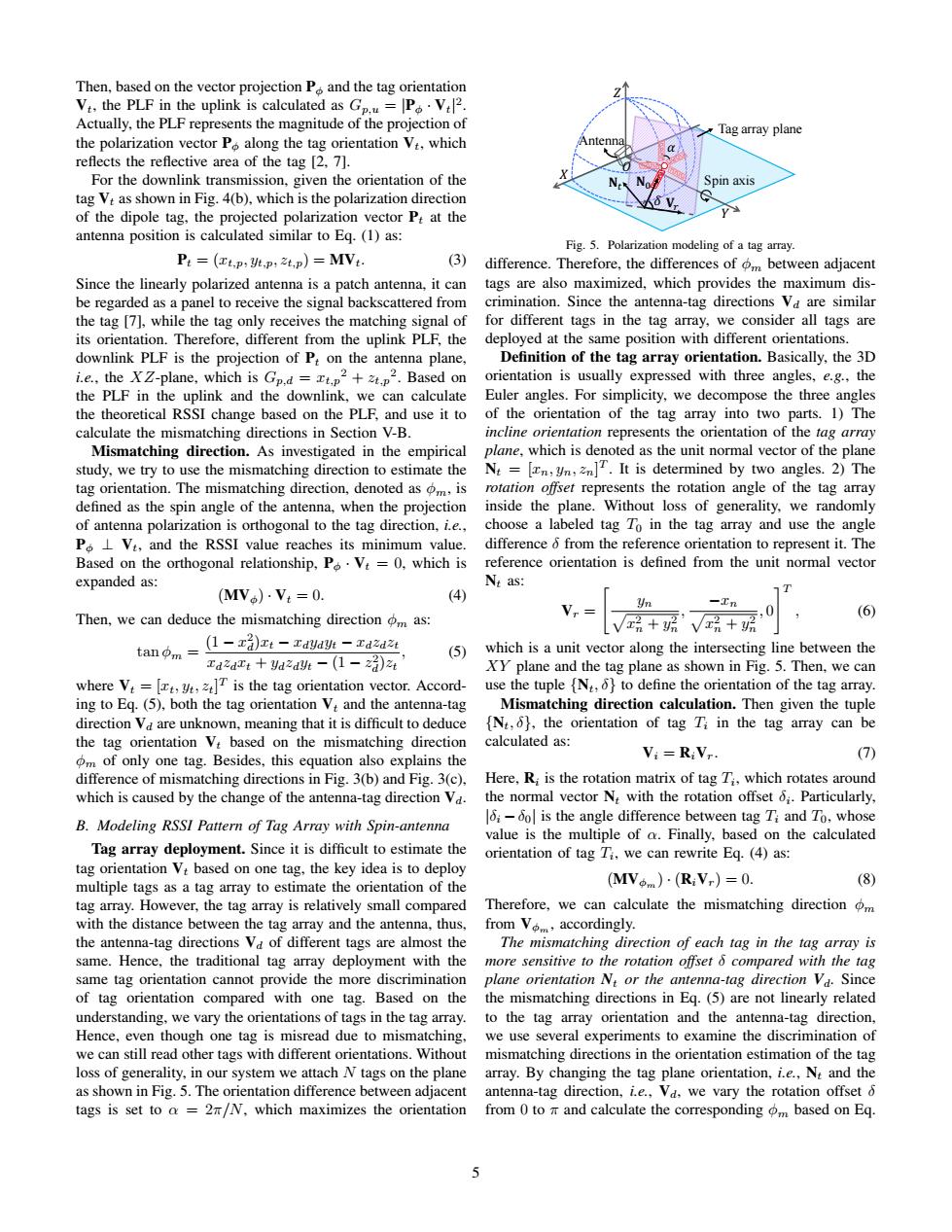
Then,based on the vector projection P and the tag orientation Vt.the PLF in the uplink is calculated as Gp.=PV2 Actually,the PLF represents the magnitude of the projection of Tag array plane the polarization vector P along the tag orientation Vt.which Antenn reflects the reflective area of the tag [2,7]. For the downlink transmission,given the orientation of the Spin axis tag Vt as shown in Fig.4(b),which is the polarization direction of the dipole tag,the projected polarization vector Pt at the antenna position is calculated similar to Eq.(1)as: Fig.5.Polarization modeling of a tag array. Pt=(xt,p,班,p2t,p)=MVt (3) difference.Therefore,the differences of om between adjacent Since the linearly polarized antenna is a patch antenna,it can tags are also maximized,which provides the maximum dis- be regarded as a panel to receive the signal backscattered from crimination.Since the antenna-tag directions Va are similar the tag [7],while the tag only receives the matching signal of for different tags in the tag array,we consider all tags are its orientation.Therefore,different from the uplink PLF,the deployed at the same position with different orientations. downlink PLF is the projection of P:on the antenna plane, Definition of the tag array orientation.Basically,the 3D i.e..the XZ-plane,which is Gp.d=.p+2.Based on orientation is usually expressed with three angles,e.g.,the the PLF in the uplink and the downlink,we can calculate Euler angles.For simplicity,we decompose the three angles the theoretical RSSI change based on the PLF,and use it to of the orientation of the tag array into two parts.1)The calculate the mismatching directions in Section V-B. incline orientation represents the orientation of the tag array Mismatching direction.As investigated in the empirical plane,which is denoted as the unit normal vector of the plane study,we try to use the mismatching direction to estimate the N=[n,.It is determined by two angles.2)The tag orientation.The mismatching direction,denoted as om,is rotation offset represents the rotation angle of the tag array defined as the spin angle of the antenna,when the projection inside the plane.Without loss of generality,we randomly of antenna polarization is orthogonal to the tag direction,i.e., choose a labeled tag To in the tag array and use the angle PL Vt,and the RSSI value reaches its minimum value. difference 6 from the reference orientation to represent it.The Based on the orthogonal relationship,Po.V:=0,which is reference orientation is defined from the unit normal vector expanded as: Nt as: (MV。).Vt=0. (4) T Then,we can deduce the mismatching direction m as: Vr= -In 21 ,0 (6 tann=-r4-zau跳-zaa4 V品+乐'√品+ (5) which is a unit vector along the intersecting line between the TdzdTt yazayt -(1-z3)zi XY plane and the tag plane as shown in Fig.5.Then,we can where V:=[t,yt,T is the tag orientation vector.Accord- use the tuple [N,6}to define the orientation of the tag array. ing to Eq.(5),both the tag orientation V:and the antenna-tag Mismatching direction calculation.Then given the tuple direction Va are unknown,meaning that it is difficult to deduce [N:,6},the orientation of tag Ti in the tag array can be the tag orientation V:based on the mismatching direction calculated as: om of only one tag.Besides,this equation also explains the Vi=RiVr. (7) difference of mismatching directions in Fig.3(b)and Fig.3(c). Here,R;is the rotation matrix of tag Ti,which rotates around which is caused by the change of the antenna-tag direction Va. the normal vector N,with the rotation offset 6.Particularly, B.Modeling RSSI Pattern of Tag Array with Spin-antenna 16i-6ol is the angle difference between tag Ti and To,whose value is the multiple of a.Finally,based on the calculated Tag array deployment.Since it is difficult to estimate the orientation of tag Ti,we can rewrite Eq.(4)as: tag orientation Vt based on one tag,the key idea is to deploy multiple tags as a tag array to estimate the orientation of the (MVom)·(R:Vr)=0. (8) tag array.However,the tag array is relatively small compared Therefore,we can calculate the mismatching direction om with the distance between the tag array and the antenna,thus, from Vo,accordingly. the antenna-tag directions Va of different tags are almost the The mismatching direction of each tag in the tag array is same.Hence,the traditional tag array deployment with the more sensitive to the rotation offset 6 compared with the tag same tag orientation cannot provide the more discrimination plane orientation N:or the antenna-tag direction Va.Since of tag orientation compared with one tag.Based on the the mismatching directions in Eq.(5)are not linearly related understanding,we vary the orientations of tags in the tag array. to the tag array orientation and the antenna-tag direction, Hence,even though one tag is misread due to mismatching, we use several experiments to examine the discrimination of we can still read other tags with different orientations.Without mismatching directions in the orientation estimation of the tag loss of generality,in our system we attach N tags on the plane array.By changing the tag plane orientation,i.e.,N:and the as shown in Fig.5.The orientation difference between adjacent antenna-tag direction,ie.,Vd,we vary the rotation offset 6 tags is set to a =2m/N,which maximizes the orientation from 0 to and calculate the corresponding om based on Eq. 5Then, based on the vector projection Pφ and the tag orientation Vt, the PLF in the uplink is calculated as Gp,u = |Pφ · Vt| 2 . Actually, the PLF represents the magnitude of the projection of the polarization vector Pφ along the tag orientation Vt, which reflects the reflective area of the tag [2, 7]. For the downlink transmission, given the orientation of the tag Vt as shown in Fig. 4(b), which is the polarization direction of the dipole tag, the projected polarization vector Pt at the antenna position is calculated similar to Eq. (1) as: Pt = (xt,p, yt,p, zt,p) = MVt. (3) Since the linearly polarized antenna is a patch antenna, it can be regarded as a panel to receive the signal backscattered from the tag [7], while the tag only receives the matching signal of its orientation. Therefore, different from the uplink PLF, the downlink PLF is the projection of Pt on the antenna plane, i.e., the XZ-plane, which is Gp,d = xt,p 2 + zt,p 2 . Based on the PLF in the uplink and the downlink, we can calculate the theoretical RSSI change based on the PLF, and use it to calculate the mismatching directions in Section V-B. Mismatching direction. As investigated in the empirical study, we try to use the mismatching direction to estimate the tag orientation. The mismatching direction, denoted as φm, is defined as the spin angle of the antenna, when the projection of antenna polarization is orthogonal to the tag direction, i.e., Pφ ⊥ Vt, and the RSSI value reaches its minimum value. Based on the orthogonal relationship, Pφ · Vt = 0, which is expanded as: (MVφ) · Vt = 0. (4) Then, we can deduce the mismatching direction φm as: tan φm = (1 − x 2 d )xt − xdydyt − xdzdzt xdzdxt + ydzdyt − (1 − z 2 d )zt , (5) where Vt = [xt, yt, zt] T is the tag orientation vector. According to Eq. (5), both the tag orientation Vt and the antenna-tag direction Vd are unknown, meaning that it is difficult to deduce the tag orientation Vt based on the mismatching direction φm of only one tag. Besides, this equation also explains the difference of mismatching directions in Fig. 3(b) and Fig. 3(c), which is caused by the change of the antenna-tag direction Vd. B. Modeling RSSI Pattern of Tag Array with Spin-antenna Tag array deployment. Since it is difficult to estimate the tag orientation Vt based on one tag, the key idea is to deploy multiple tags as a tag array to estimate the orientation of the tag array. However, the tag array is relatively small compared with the distance between the tag array and the antenna, thus, the antenna-tag directions Vd of different tags are almost the same. Hence, the traditional tag array deployment with the same tag orientation cannot provide the more discrimination of tag orientation compared with one tag. Based on the understanding, we vary the orientations of tags in the tag array. Hence, even though one tag is misread due to mismatching, we can still read other tags with different orientations. Without loss of generality, in our system we attach N tags on the plane as shown in Fig. 5. The orientation difference between adjacent tags is set to α = 2π/N, which maximizes the orientation � � � Antenna Tag array plane � � Spin axis & � � �* �+ Fig. 5. Polarization modeling of a tag array. difference. Therefore, the differences of φm between adjacent tags are also maximized, which provides the maximum discrimination. Since the antenna-tag directions Vd are similar for different tags in the tag array, we consider all tags are deployed at the same position with different orientations. Definition of the tag array orientation. Basically, the 3D orientation is usually expressed with three angles, e.g., the Euler angles. For simplicity, we decompose the three angles of the orientation of the tag array into two parts. 1) The incline orientation represents the orientation of the tag array plane, which is denoted as the unit normal vector of the plane Nt = [xn, yn, zn] T . It is determined by two angles. 2) The rotation offset represents the rotation angle of the tag array inside the plane. Without loss of generality, we randomly choose a labeled tag T0 in the tag array and use the angle difference δ from the reference orientation to represent it. The reference orientation is defined from the unit normal vector Nt as: Vr = " p yn x 2 n + y 2 n , p −xn x 2 n + y 2 n , 0 #T , (6) which is a unit vector along the intersecting line between the XY plane and the tag plane as shown in Fig. 5. Then, we can use the tuple {Nt, δ} to define the orientation of the tag array. Mismatching direction calculation. Then given the tuple {Nt, δ}, the orientation of tag Ti in the tag array can be calculated as: Vi = RiVr. (7) Here, Ri is the rotation matrix of tag Ti , which rotates around the normal vector Nt with the rotation offset δi . Particularly, |δi −δ0| is the angle difference between tag Ti and T0, whose value is the multiple of α. Finally, based on the calculated orientation of tag Ti , we can rewrite Eq. (4) as: (MVφm) · (RiVr) = 0. (8) Therefore, we can calculate the mismatching direction φm from Vφm, accordingly. The mismatching direction of each tag in the tag array is more sensitive to the rotation offset δ compared with the tag plane orientation Nt or the antenna-tag direction Vd. Since the mismatching directions in Eq. (5) are not linearly related to the tag array orientation and the antenna-tag direction, we use several experiments to examine the discrimination of mismatching directions in the orientation estimation of the tag array. By changing the tag plane orientation, i.e., Nt and the antenna-tag direction, i.e., Vd, we vary the rotation offset δ from 0 to π and calculate the corresponding φm based on Eq. 5