正在加载图片...
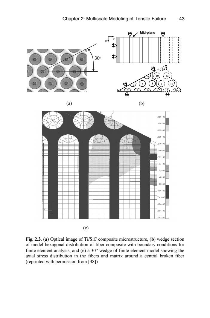
Chapter 2:Multiscale Modeling of Tensile Failure 43 Mid-plane 309 .6 (a) (b) 369+03 344+03 3t9+03 296+03 70+3 16+0 1+0 97+0 2+ 48+0 2340 986+0 41+00 96402 251+0 583400 (c) Fig.2.3.(a)Optical image of Ti/SiC composite microstructure,(b)wedge section of model hexagonal distribution of fiber composite with boundary conditions for finite element analysis,and (c)a 30 wedge of finite element model showing the axial stress distribution in the fibers and matrix around a central broken fiber (reprinted with permission from [38])(c) Fig. 2.3. (a) Optical image of Ti/SiC composite microstructure, (b) wedge section of model hexagonal distribution of fiber composite with boundary conditions for finite element analysis, and (c) a 30° wedge of finite element model showing the axial stress distribution in the fibers and matrix around a central broken fiber 43 (a) (b) 30o z r 2 5 3 4 8 6 9 10 11 1 7 12 16 15 14 13 Mid-plane z r 2 5 3 4 8 6 9 10 11 1 7 12 16 15 14 13 2 5 3 4 8 6 9 10 11 1 7 12 16 15 14 13 2 5 3 4 8 6 9 10 11 1 7 12 16 15 14 13 Mid-plane Chapter 2: Multiscale Modeling of Tensile Failure (reprinted with permission from [38])