正在加载图片...
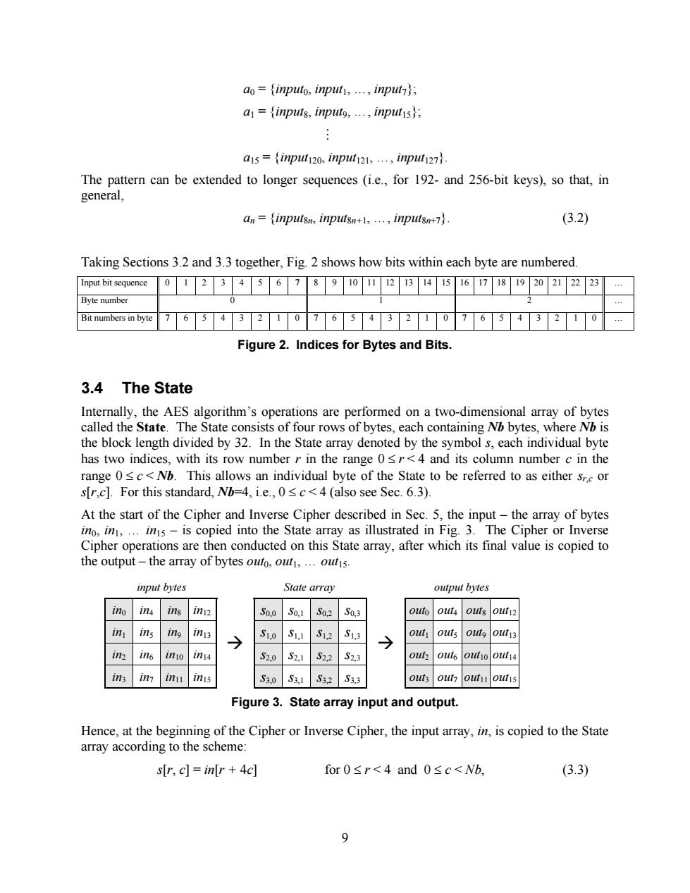
ao=inputo,input,...,input; a=inputs,input9,...inputs; a15={inp120,inpl121,…,inpl127}. The pattern can be extended to longer sequences (i.e.,for 192-and 256-bit keys),so that,in general, an=inputsn,inputsn+1,...,inputsn+7. (3.2) Taking Sections 3.2 and 3.3 together,Fig.2 shows how bits within each byte are numbered. Input bit sequence 01234678902B45678920222 23 Byte number Bit numbers in byte 76543210765432107654 2 Figure 2.Indices for Bytes and Bits 3.4 The State Internally,the AES algorithm's operations are performed on a two-dimensional array of bytes called the State.The State consists of four rows of bytes,each containing Nb bytes,where Nb is the block length divided by 32.In the State array denoted by the symbol s,each individual byte has two indices,with its row number r in the range 0<r<4 and its column number c in the range 0sc<Nb.This allows an individual byte of the State to be referred to as either sr.c or s[r,c].For this standard,Nb=4,i.e.,0sc<4 (also see Sec.6.3). At the start of the Cipher and Inverse Cipher described in Sec.5,the input-the array of bytes ino,in,...ins-is copied into the State array as illustrated in Fig.3.The Cipher or Inverse Cipher operations are then conducted on this State array,after which its final value is copied to the output-the array of bytes outo,out,...outis. input bytes State array output bytes ino 1n4 ins in12 S0,0S0,1 S0,2 50,3 outo out4 outs out12 in ins ing iny3 → S1,0S1,1 S12 S1,3 out outs outg out13 in In6 inio in14 S2.0 S2,1 S22 S2,3 out out6 out14 1n3 1 m11 inis S3.0S3,1 S32 S3,3 out out outu out1s Figure 3.State array input and output. Hence,at the beginning of the Cipher or Inverse Cipher,the input array,in,is copied to the State array according to the scheme: s[r,c]=in[r 4c] for0≤r<4and0≤c<Wb, (3.3) 99 a0 = {input0, input1, …, input7}; a1 = {input8, input9, …, input15}; M a15 = {input120, input121, …, input127}. The pattern can be extended to longer sequences (i.e., for 192- and 256-bit keys), so that, in general, an = {input8n, input8n+1, …, input8n+7}. (3.2) Taking Sections 3.2 and 3.3 together, Fig. 2 shows how bits within each byte are numbered. Input bit sequence 0 1 2 3 4 5 6 7 8 9 10 11 12 13 14 15 16 17 18 19 20 21 22 23 … Byte number 0 1 2 … Bit numbers in byte 7 6 5 4 3 2 1 0 7 6 5 4 3 2 1 0 7 6 5 4 3 2 1 0 … Figure 2. Indices for Bytes and Bits. 3.4 The State Internally, the AES algorithm’s operations are performed on a two-dimensional array of bytes called the State. The State consists of four rows of bytes, each containing Nb bytes, where Nb is the block length divided by 32. In the State array denoted by the symbol s, each individual byte has two indices, with its row number r in the range 0 £ r < 4 and its column number c in the range 0 £ c < Nb. This allows an individual byte of the State to be referred to as either sr,c or s[r,c]. For this standard, Nb=4, i.e., 0 £ c < 4 (also see Sec. 6.3). At the start of the Cipher and Inverse Cipher described in Sec. 5, the input – the array of bytes in0, in1, … in15 – is copied into the State array as illustrated in Fig. 3. The Cipher or Inverse Cipher operations are then conducted on this State array, after which its final value is copied to the output – the array of bytes out0, out1, … out15. input bytes State array output bytes in0 in4 in8 in12 s0,0 s0,1 s0,2 s0,3 out0 out4 out8 out12 in1 in5 in9 in13 s1,0 s1,1 s1,2 s1,3 out1 out5 out9 out13 in2 in6 in10 in14 s2,0 s2,1 s2,2 s2,3 out2 out6 out10 out14 in3 in7 in11 in15 ‡ s3,0 s3,1 s3,2 s3,3 ‡ out3 out7 out11 out15 Figure 3. State array input and output. Hence, at the beginning of the Cipher or Inverse Cipher, the input array, in, is copied to the State array according to the scheme: s[r, c] = in[r + 4c] for 0 £ r < 4 and 0 £ c < Nb, (3.3)