正在加载图片...
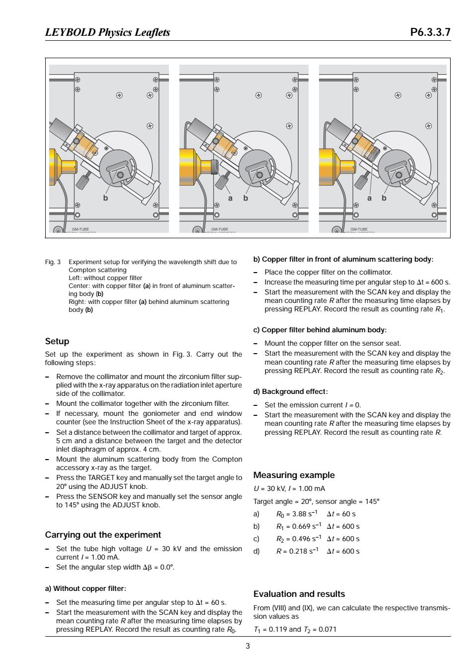
LEYBOLD Physics Leaflets P6.3.3.7 GM-TUBE GM-TUBE GM-TUBE Fig.3 Experiment setup for verifying the wavelength shift due to b)Copper filter in front of aluminum scattering body: Compton scattering Place the copper filter on the collimator. Left:without copper filter Center:with copper filter(a)in front of aluminum scatter- 、 Increase the measuring time per angular step to At=600 s ing body(b) Start the measurement with the SCAN key and display the Right:with copper filter(a)behind aluminum scattering mean counting rate R after the measuring time elapses by body (b) pressing REPLAY.Record the result as counting rate R1. c)Copper filter behind aluminum body: Setup Mount the copper filter on the sensor seat. Set up the experiment as shown in Fig.3.Carry out the Start the measurement with the SCAN key and display the following steps: mean counting rate R after the measuring time elapses by pressing REPLAY.Record the result as counting rate R2. Remove the collimator and mount the zirconium filter sup- plied with the x-ray apparatus on the radiation inlet aperture side of the collimator. d)Background effect: Mount the collimator together with the zirconium filter. Set the emission current /=0. If necessary.mount the goniometer and end window Start the measurement with the SCAN key and display the counter (see the Instruction Sheet of the x-ray apparatus). mean counting rate R after the measuring time elapses by Set a distance between the collimator and target of approx. pressing REPLAY.Record the result as counting rate R. 5 cm and a distance between the target and the detector inlet diaphragm of approx.4 cm. Mount the aluminum scattering body from the Compton accessory x-ray as the target. Press the TARGET key and manually set the target angle to Measuring example 20using the ADJUST knob. U=30kV,/=1.00mA Press the SENSOR key and manually set the sensor angle to 145 using the ADJUST knob. Target angle-2o°,sensor angle=145 a)R=3.88s-1△t=60s b) R1=0.669s-1△t=600s Carrying out the experiment c R2=0.496s-1△t=600s Set the tube high voltage U=30 kV and the emission d R=0.218s-1△t=600s current /1.00 mA. -Set the angular step width△B=O.o°. a)Without copper filter: Evaluation and results Set the measuring time per angular step to At =60 s. Start the measurement with the SCAN key and display the From (VIll)and(IX),we can calculate the respective transmis- mean counting rate R after the measuring time elapses by sion values as pressing REPLAY.Record the result as counting rate Ro T1=0.119andT2=0.071 3Setup Set up the experiment as shown in Fig. 3. Carry out the following steps: – Remove the collimator and mount the zirconium filter supplied with the x-ray apparatus on the radiation inlet aperture side of the collimator. – Mount the collimator together with the zirconium filter. – If necessary, mount the goniometer and end window counter (see the Instruction Sheet of the x-ray apparatus). – Set a distance between the collimator and target of approx. 5 cm and a distance between the target and the detector inlet diaphragm of approx. 4 cm. – Mount the aluminum scattering body from the Compton accessory x-ray as the target. – Press the TARGET key and manually set the target angle to 208 using the ADJUST knob. – Press the SENSOR key and manually set the sensor angle to 1458 using the ADJUST knob. Carrying out the experiment – Set the tube high voltage U = 30 kV and the emission current I = 1.00 mA. – Set the angular step width Db = 0.08. a) Without copper filter: – Set the measuring time per angular step to Dt = 60 s. – Start the measurement with the SCAN key and display the mean counting rate R after the measuring time elapses by pressing REPLAY. Record the result as counting rate R0. b) Copper filter in front of aluminum scattering body: – Place the copper filter on the collimator. – Increase the measuring time per angular step to Dt = 600 s. – Start the measurement with the SCAN key and display the mean counting rate R after the measuring time elapses by pressing REPLAY. Record the result as counting rate R1. c) Copper filter behind aluminum body: – Mount the copper filter on the sensor seat. – Start the measurement with the SCAN key and display the mean counting rate R after the measuring time elapses by pressing REPLAY. Record the result as counting rate R2. d) Background effect: – Set the emission current I = 0. – Start the measurement with the SCAN key and display the mean counting rate R after the measuring time elapses by pressing REPLAY. Record the result as counting rate R. Measuring example U = 30 kV, I = 1.00 mA Target angle = 208, sensor angle = 1458 a) R0 = 3.88 s–1 Dt = 60 s b) R1 = 0.669 s–1 Dt = 600 s c) R2 = 0.496 s–1 Dt = 600 s d) R = 0.218 s–1 Dt = 600 s Evaluation and results From (VIII) and (IX), we can calculate the respective transmission values as T1 = 0.119 and T2 = 0.071 Fig. 3 Experiment setup for verifying the wavelength shift due to Compton scattering Left: without copper filter Center: with copper filter (a) in front of aluminum scattering body (b) Right: with copper filter (a) behind aluminum scattering body (b) LEYBOLD Physics Leaflets P6.3.3.7 3