正在加载图片...
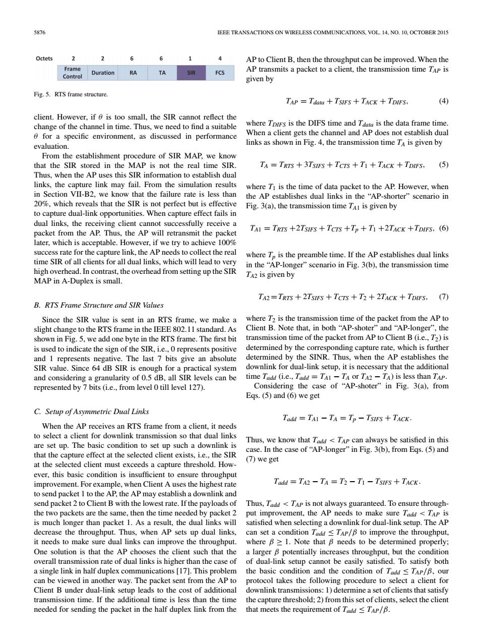
5s76 IEEE TRANSACTIONS ON WIRELESS COMMUNICATIONS.VOL 14.NO.10.OCTOBER 2015 Octets 2 6 6 1 AP to Client B,then the throughput can be improved.When the Frame Duration RA TA SIR FCS AP transmits a packet to a client,the transmission time TAp is given by Fig 5.RTS frames ructu TAP=Tdata TsIFS TACK TDIFS. client.Hov thever.if o where is the DIFS time and Ta for a specific environment.as discussed in performance evaluation. is given b establishment pro cedure of SIR MAP we kn the Ap us is not th rea (5 this SIR i links,the capture link may fail.From the simulation results where T is th in Section VII-B2,we know that the failure rate is less than n the 0% s that th Wot perfe Fig.3(a).the transmission time T is given by dual links.the receiving client fwe try toa ieve 100 fal。he r ne e re where T is the preamble time.If the AP establishes dual links hish overhead.In contrast.the overhead from setting up the SIR in the"AP-longer"scenario in Fig.3(b),the transmission time A2 is given by MAP in A-Duplex is small. TA2=TRTS +2TsIFs +Tcrs +T2 +2TAck +TDIFS.(T) B.RTS Frame Structure and SIR Value Since the SIR value is sent in an RTS frame,we make a wheres time of the packet from the APto slight changetothe RTS frame in the TEE acket from APto Clent B (i .we rame determined by the co onding capture rate,which is furthe and I represents negative.The last 7 bits give an abolute determined by the SINR Thus .when the AP stablishes the SIR value.Since 64 dB SIR is enough for a lual-link S tup.it is ne els can be (ie repre 127 Eas.(5)and (6)we get C.Setup of Asvmmetric Dual Links Tadd =TAI-TA=Tp-TsIEs+TACk for do re set un The hasie condition to set un such a downlink is Thus.we know that T<TAp can always be satisfied in this that the capture effect at the selected client exists. case.In the case of"AP-longer"in Fig.3(b).from Eqs.(5)and (7)we ge at the must exce capture thre Todd=TA2-TA=T3-TI-TsIEs+TACk. to send packet I to the AP.the AP may establish a dowr nlink and e the s e.then the w sel the TAP AP decrease the throughput.Thus.when AP sets up dual links can set a condition T <to improve the throughpu it needs to make sure dual links can improve the throughput. where B1.Note that B needs to be determined properly: that the AP s the clier such that the ngle link in hal be eas. [1 This the has up cann of T can be viewed in another way.The packet sent from the AP to protocol takes the following procedure to select a client for s to the ost of than the time s.select the clien T.85876 IEEE TRANSACTIONS ON WIRELESS COMMUNICATIONS, VOL. 14, NO. 10, OCTOBER 2015 Fig. 5. RTS frame structure. client. However, if θ is too small, the SIR cannot reflect the change of the channel in time. Thus, we need to find a suitable θ for a specific environment, as discussed in performance evaluation. From the establishment procedure of SIR MAP, we know that the SIR stored in the MAP is not the real time SIR. Thus, when the AP uses this SIR information to establish dual links, the capture link may fail. From the simulation results in Section VII-B2, we know that the failure rate is less than 20%, which reveals that the SIR is not perfect but is effective to capture dual-link opportunities. When capture effect fails in dual links, the receiving client cannot successfully receive a packet from the AP. Thus, the AP will retransmit the packet later, which is acceptable. However, if we try to achieve 100% success rate for the capture link, the AP needs to collect the real time SIR of all clients for all dual links, which will lead to very high overhead. In contrast, the overhead from setting up the SIR MAP in A-Duplex is small. B. RTS Frame Structure and SIR Values Since the SIR value is sent in an RTS frame, we make a slight change to the RTS frame in the IEEE 802.11 standard. As shown in Fig. 5, we add one byte in the RTS frame. The first bit is used to indicate the sign of the SIR, i.e., 0 represents positive and 1 represents negative. The last 7 bits give an absolute SIR value. Since 64 dB SIR is enough for a practical system and considering a granularity of 0.5 dB, all SIR levels can be represented by 7 bits (i.e., from level 0 till level 127). C. Setup of Asymmetric Dual Links When the AP receives an RTS frame from a client, it needs to select a client for downlink transmission so that dual links are set up. The basic condition to set up such a downlink is that the capture effect at the selected client exists, i.e., the SIR at the selected client must exceeds a capture threshold. However, this basic condition is insufficient to ensure throughput improvement. For example, when Client A uses the highest rate to send packet 1 to the AP, the AP may establish a downlink and send packet 2 to Client B with the lowest rate. If the payloads of the two packets are the same, then the time needed by packet 2 is much longer than packet 1. As a result, the dual links will decrease the throughput. Thus, when AP sets up dual links, it needs to make sure dual links can improve the throughput. One solution is that the AP chooses the client such that the overall transmission rate of dual links is higher than the case of a single link in half duplex communications [17]. This problem can be viewed in another way. The packet sent from the AP to Client B under dual-link setup leads to the cost of additional transmission time. If the additional time is less than the time needed for sending the packet in the half duplex link from the AP to Client B, then the throughput can be improved. When the AP transmits a packet to a client, the transmission time TAP is given by TAP = Tdata + TSIFS + TACK + TDIFS, (4) where TDIFS is the DIFS time and Tdata is the data frame time. When a client gets the channel and AP does not establish dual links as shown in Fig. 4, the transmission time TA is given by TA = TRTS + 3TSIFS + TCTS + T1 + TACK + TDIFS, (5) where T1 is the time of data packet to the AP. However, when the AP establishes dual links in the “AP-shorter” scenario in Fig. 3(a), the transmission time TA1 is given by TA1 = TRTS +2TSIFS + TCTS +Tp + T1 +2TACK +TDIFS, (6) where Tp is the preamble time. If the AP establishes dual links in the “AP-longer” scenario in Fig. 3(b), the transmission time TA2 is given by TA2 =TRTS + 2TSIFS + TCTS + T2 + 2TACK + TDIFS, (7) where T2 is the transmission time of the packet from the AP to Client B. Note that, in both “AP-shoter” and “AP-longer”, the transmission time of the packet from AP to Client B (i.e., T2) is determined by the corresponding capture rate, which is further determined by the SINR. Thus, when the AP establishes the downlink for dual-link setup, it is necessary that the additional time Tadd (i.e., Tadd = TA1 − TA or TA2 − TA) is less than TAP. Considering the case of “AP-shoter” in Fig. 3(a), from Eqs. (5) and (6) we get Tadd = TA1 − TA = Tp − TSIFS + TACK. Thus, we know that Tadd < TAP can always be satisfied in this case. In the case of “AP-longer” in Fig. 3(b), from Eqs. (5) and (7) we get Tadd = TA2 − TA = T2 − T1 − TSIFS + TACK. Thus, Tadd < TAP is not always guaranteed. To ensure throughput improvement, the AP needs to make sure Tadd < TAP is satisfied when selecting a downlink for dual-link setup. The AP can set a condition Tadd ≤ TAP/β to improve the throughput, where β ≥ 1. Note that β needs to be determined properly; a larger β potentially increases throughput, but the condition of dual-link setup cannot be easily satisfied. To satisfy both the basic condition and the condition of Tadd ≤ TAP/β, our protocol takes the following procedure to select a client for downlink transmissions: 1) determine a set of clients that satisfy the capture threshold; 2) from this set of clients, select the client that meets the requirement of Tadd ≤ TAP/β