正在加载图片...

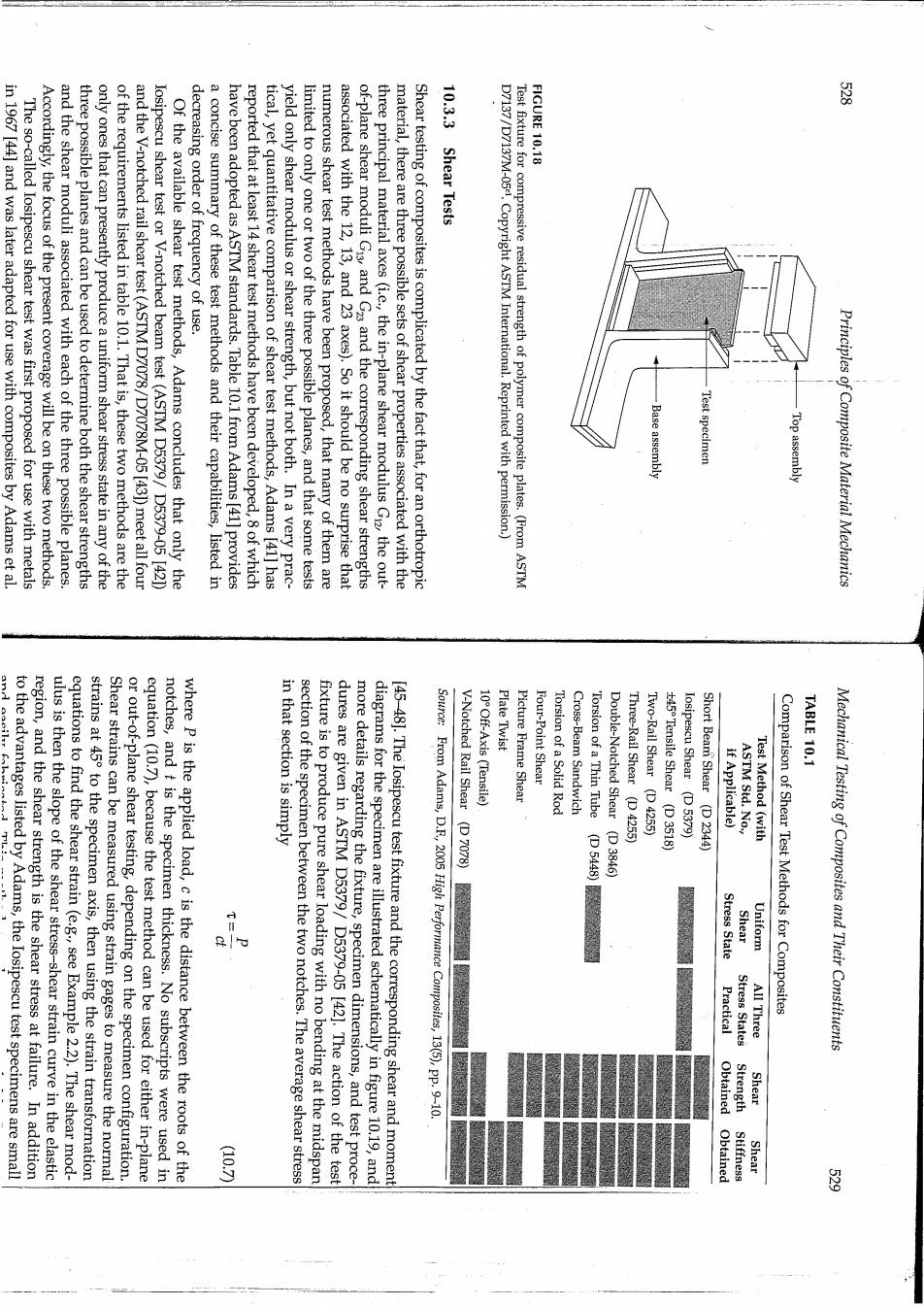
FIGURE 10.18 图 in 1967 [44]and was later adapted for use with composites by Adams et al. The so-called losipescu shear test was first proposed for use with metals Accordingly,the focus of the present coverage will be on these two methods. and the shear moduli associated with each of the three possible planes. three possible planes and can be used to determine both the shear strengths only ones that can presently produce a uniform shear stress state in any of the of the requirements listed in table 10.1.That is,these two methods are the and the V-notched rail shear test(ASTM D7078/D7078M-05 [43])meet all four losipescu shear test or V-notched beam test (ASTM D5379/D5379-05 42) Of the available shear test methods,Adams concludes that only the decreasing order of frequency of use. a concise summary of these test methods and their capabilities,listed in have been adopted as ASTM standards.Table 10.1 from Adams [41]provides reported that at least 14 shear test methods have been developed,8 of which tical,yet quantitative comparison of shear test methods,Adams [41]has yield only shear modulus or shear strength,but not both.In a very prac- limited to only one or two of the three possible planes,and that some tests numerous shear test methods have been proposed,that many of them are associated with the 12,13,and 23 axes).So it should be no surprise that of-plane shear moduli Gis and G2 and the corresponding shear strengths three principal material axes (i.e.,the in-plane shear modulus Gi2,the out- material,there are three possible sets of shear properties associated with the Shear testing of composites is complicated by the fact that,for an orthotropic 10.3.3 Shear Tests D7137/D7137M-05.Copyright ASTM International.Reprinted with permission.) Test fixture for compressive residual strength of polymer composite plates.(From ASTM se assembly Test specimen Top assembly Principles of Composite Material Mechanics Plate Twist Four-Point Shear TABLE 10.1 to the advantages listed by Adams,the Iosipescu test specimens are small region,and the shear strength is the shear stress at failure.In addition ulus is then the slope of the shear stress-shear strain curve in the elastic equations to find the shear strain (e.g.,see Example 2.2).The shear mod- Shear strains can be measured using strain gages to measure the normal strains at 45 to the specimen axis,then using the strain transformation or out-of-plane shear testing,depending on the specimen configuration. equation(10.7),because the test method can be used for either in-plane notches,and t is the specimen thickness.No subscripts were used in where p is the applied load,c is the distance between the roots of the section of the specimen between the two notches.The average shear stress in that section is simply fixture is to produce pure shear loading with no bending at the midspan dures are given in ASTM D5379/D5379-05 [42].The action of the test more details regarding the fixture,specimen dimensions,and test proce- diagrams for the specimen are illustrated schematically in figure 10.19,and [45-48].The Iosipescu test fixture and the corresponding shear and moment Source:From Adams,D.F,2005 High Performance Composites,13(5),pp.9-10 V-(D70效》V- 10 Off-Axis (Tensile) Picture Frame Shear Torsion of a Solid Rod Cross-Beam Sandwich Torsion of a Thin Tube Double-Notched Shear (D 3846) Three-Rail Shear (D 4255) Two-Rail Shear (D 4255) t45 Tensile Shear (D 3518) losipescu Shear (D 5379) Short Beam Shear (D 2344) if Applicable) ASTM Std.No., Test Method (with Stress State Shear Uniform Comparison of Shear Test Methods for Composites Mechanical Testing of Composites and Their Constituents Practical Stress States A晶Tree Obtained Strength Shear Obtained Stiffness Shear 留