正在加载图片...
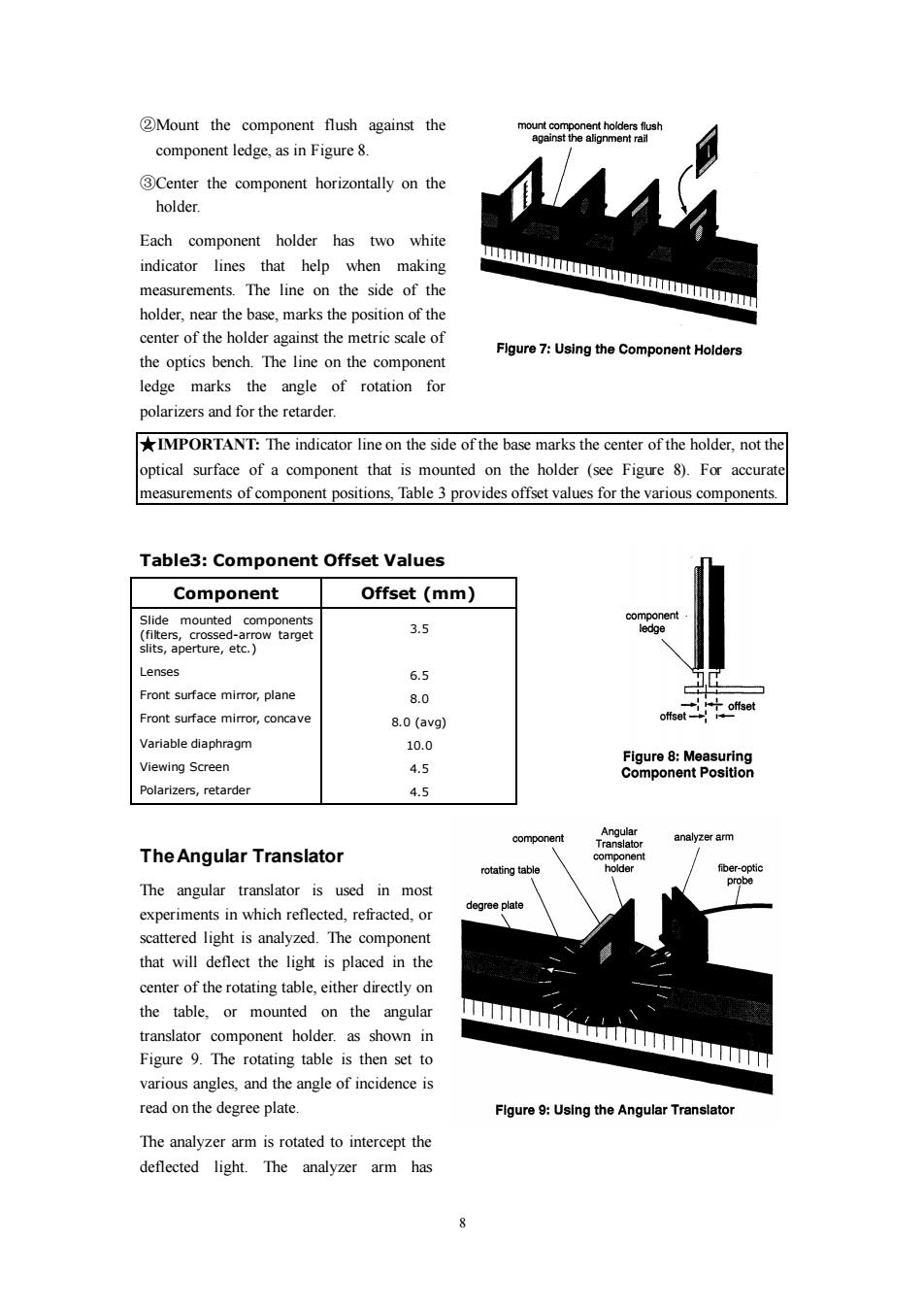
2Mount the component flush against the mount component holders flush against the alignment rail component ledge,as in Figure 8. 3Center the component horizontally on the holder. Each component holder has two white indicator lines that help when making measurements.The line on the side of the mmm holder,near the base,marks the position of the center of the holder against the metric scale of Figure 7:Using the Component Holders the optics bench.The line on the component ledge marks the angle of rotation for polarizers and for the retarder. IMPORTANT:The indicator line on the side of the base marks the center of the holder,not the optical surface of a component that is mounted on the holder (see Figure 8).For accurate measurements of component positions,Table 3 provides offset values for the various components. Table3:Component Offset Values Component Offset(mm) Slide mounted components component (filters,crossed-arrow target 3.5 ledge slits,aperture,etc. Lenses 6.5 Front surface mirror,plane 8.0 offset offset Front surface mirror,concave 8.0(avg) Variable diaphragm 10.0 Figure 8:Measuring Viewing Screen 4.5 Component Position Polarizers,retarder 4.5 Angular component analyzer arm Translator The Angular Translator component rotating table holder f他er-optic The angular translator is used in most probe experiments in which reflected,refracted,or degree plate scattered light is analyzed.The component that will deflect the light is placed in the center of the rotating table,either directly on the table,or mounted on the angular translator component holder.as shown in Figure 9.The rotating table is then set to various angles,and the angle of incidence is read on the degree plate. Flgure 9:Using the Angular Translator The analyzer arm is rotated to intercept the deflected light.The analyzer arm has 88 ②Mount the component flush against the component ledge, as in Figure 8. ③Center the component horizontally on the holder. Each component holder has two white indicator lines that help when making measurements. The line on the side of the holder, near the base, marks the position of the center of the holder against the metric scale of the optics bench. The line on the component ledge marks the angle of rotation for polarizers and for the retarder. ★IMPORTANT: The indicator line on the side of the base marks the center of the holder, not the optical surface of a component that is mounted on the holder (see Figure 8). For accurate measurements of component positions, Table 3 provides offset values for the various components. Table3: Component Offset Values Component Offset (mm) Slide mounted components (filters, crossed-arrow target slits, aperture, etc.) Lenses Front surface mirror, plane Front surface mirror, concave Variable diaphragm Viewing Screen Polarizers, retarder 3.5 6.5 8.0 8.0 (avg) 10.0 4.5 4.5 The Angular Translator The angular translator is used in most experiments in which reflected, refracted, or scattered light is analyzed. The component that will deflect the light is placed in the center of the rotating table, either directly on the table, or mounted on the angular translator component holder. as shown in Figure 9. The rotating table is then set to various angles, and the angle of incidence is read on the degree plate. The analyzer arm is rotated to intercept the deflected light. The analyzer arm has