正在加载图片...
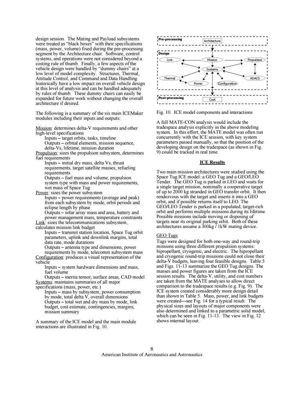
design session.The Mating and Payload subsystems Pre-processing Architecture were treated as"black boxes"with their specifications (mass,power,volume)fixed during the pre-processing segment by the Architecture chair.Software,control Design systems,and operations were not considered beyond a Link sion Propulsion costing rule of thumb.Finally,a few aspects of the vehicle design were handled by"dummy chairs"at a Svst low level of model complexity.Structures,Thermal, Attitude Control,and Command and Data Handling Thermal ADACS historically have a low impact on overall vehicle design Power Configuration at this level of analysis and can be handled adequately by rules of thumb.These dummy chairs can easily be expanded for future work without changing the overall Post-processing Cost architecture if desired. The following is a summary of the six main ICEMaker Fig.10.ICE model components and interactions modules including their inputs and outputs: A full MATE-CON analysis would include the Mission:determines delta-V requirements and other tradespace analysis explicitly in the above modeling high-level specifications system.In this effort,the MATE model was often run Inputs-target orbits,tasks,timeline concurrently with the ICE session,with key system Outputs-orbital elements,mission sequence, parameters passed manually,so that the position of the delta-Vs,lifetime,mission duration developing design on the tradespace (as shown in Fig. Propulsion:sizes the propulsion subsystem,determines 9)could be tracked in real time. fuel requirements Inputs-initial dry mass,delta Vs,thrust ICE Results requirements,target satellite masses,refueling requirements Two main mission architectures were studied using the Outputs-fuel mass and volume,propulsion Space Tug ICE model:a GEO Tug and a GEO/LEO system type with mass and power requirements, Tender.The GEO Tug is parked in LEO and waits for wet mass of Space Tug a single target mission,nominally a cooperative target Power:sizes the power subsystem of up to 2000 kg stranded in GEO transfer orbit.It then Inputs-power requirements (average and peak) rendezvous with the target and inserts it into a GEO from each subsystem by mode,orbit periods and orbit,and if possible returns itself to LEO.The eclipse length by phase GEO/LEO Tender is parked in a populated,target-rich Outputs-solar array mass and area,battery and orbit and performs multiple missions during its lifetime power management mass,temperature constraints Possible missions include moving or disposing of Link:sizes the telecommunications subsystem. targets near its original parking orbit.Both of these calculates mission link budget architectures assume a 300kg/IkW mating device. Inputs-transmit station location,Space Tug orbit parameters,uplink and downlink margins,total GEO Tugs data rate.mode durations Tugs were designed for both one-way and round-trip Outputs-antenna type and dimensions,power missions using three different propulsion systems: requirements by mode,telecomm subsystem mass bipropellant,cryogenic,and electric.The bipropellant Configuration:produces a visual representation of the and cryogenic round-trip missions could not close their vehicle delta-V budgets,leaving four feasible designs.Table 5 Inputs-system hardware dimensions and mass. and Figs.11-13 summarize the GEO Tug designs.The fuel volume masses and power figures are taken from the ICE Outputs-inertia tensor,surface areas,CAD model session results.The delta-V.utility,and cost numbers Systems:maintains summaries of all major are taken from the MATE analyses to allow direct specifications (mass,power,etc. comparison to the tradespace results(e.g.Fig.9).The Inputs-mass by subsystem,power consumption ICE system created considerably more design detail by mode,total delta V,overall dimensions than shown in Table 5.Mass,power,and link budgets Outputs-total wet and dry mass by mode,link were created-see Fig.14 for a typical result.The budget,cost estimate,contingencies,margins, physical sizes and layouts of major components were mission summary also determined and linked to a parametric solid model. which can be seen in Fig.11-13.The view in Fig.12 A summary of the ICE model and the main module shows internal layout. interactions are illustrated in Fig.10. American Institute of Aeronautics and Astronautics8 American Institute of Aeronautics and Astronautics design session. The Mating and Payload subsystems were treated as “black boxes” with their specifications (mass, power, volume) fixed during the pre-processing segment by the Architecture chair. Software, control systems, and operations were not considered beyond a costing rule of thumb. Finally, a few aspects of the vehicle design were handled by “dummy chairs” at a low level of model complexity. Structures, Thermal, Attitude Control, and Command and Data Handling historically have a low impact on overall vehicle design at this level of analysis and can be handled adequately by rules of thumb. These dummy chairs can easily be expanded for future work without changing the overall architecture if desired. The following is a summary of the six main ICEMaker modules including their inputs and outputs: Mission: determines delta-V requirements and other high-level specifications Inputs – target orbits, tasks, timeline Outputs – orbital elements, mission sequence, delta-Vs, lifetime, mission duration Propulsion: sizes the propulsion subsystem, determines fuel requirements Inputs – initial dry mass, delta Vs, thrust requirements, target satellite masses, refueling requirements Outputs – fuel mass and volume, propulsion system type with mass and power requirements, wet mass of Space Tug Power: sizes the power subsystem Inputs – power requirements (average and peak) from each subsystem by mode, orbit periods and eclipse length by phase Outputs – solar array mass and area, battery and power management mass, temperature constraints Link: sizes the telecommunications subsystem, calculates mission link budget Inputs – transmit station location, Space Tug orbit parameters, uplink and downlink margins, total data rate, mode durations Outputs – antenna type and dimensions, power requirements by mode, telecomm subsystem mass Configuration: produces a visual representation of the vehicle Inputs – system hardware dimensions and mass, fuel volume Outputs – inertia tensor, surface areas, CAD model Systems: maintains summaries of all major specifications (mass, power, etc.) Inputs – mass by subsystem, power consumption by mode, total delta V, overall dimensions Outputs – total wet and dry mass by mode, link budget, cost estimate, contingencies, margins, mission summary A summary of the ICE model and the main module interactions are illustrated in Fig. 10. Fig. 10. ICE model components and interactions A full MATE-CON analysis would include the tradespace analysis explicitly in the above modeling system. In this effort, the MATE model was often run concurrently with the ICE session, with key system parameters passed manually, so that the position of the developing design on the tradespace (as shown in Fig. 9) could be tracked in real time. ICE Results Two main mission architectures were studied using the Space Tug ICE model: a GEO Tug and a GEO/LEO Tender. The GEO Tug is parked in LEO and waits for a single target mission, nominally a cooperative target of up to 2000 kg stranded in GEO transfer orbit. It then rendezvous with the target and inserts it into a GEO orbit, and if possible returns itself to LEO. The GEO/LEO Tender is parked in a populated, target-rich orbit and performs multiple missions during its lifetime. Possible missions include moving or disposing of targets near its original parking orbit. Both of these architectures assume a 300kg / 1kW mating device. GEO Tugs Tugs were designed for both one-way and round-trip missions using three different propulsion systems: bipropellant, cryogenic, and electric. The bipropellant and cryogenic round-trip missions could not close their delta-V budgets, leaving four feasible designs. Table 5 and Figs. 11-13 summarize the GEO Tug designs. The masses and power figures are taken from the ICE session results. The delta-V, utility, and cost numbers are taken from the MATE analyses to allow direct comparison to the tradespace results (e.g. Fig. 9). The ICE system created considerably more design detail than shown in Table 5. Mass, power, and link budgets were created—see Fig. 14 for a typical result. The physical sizes and layouts of major components were also determined and linked to a parametric solid model, which can be seen in Fig. 11-13. The view in Fig. 12 shows internal layout