正在加载图片...
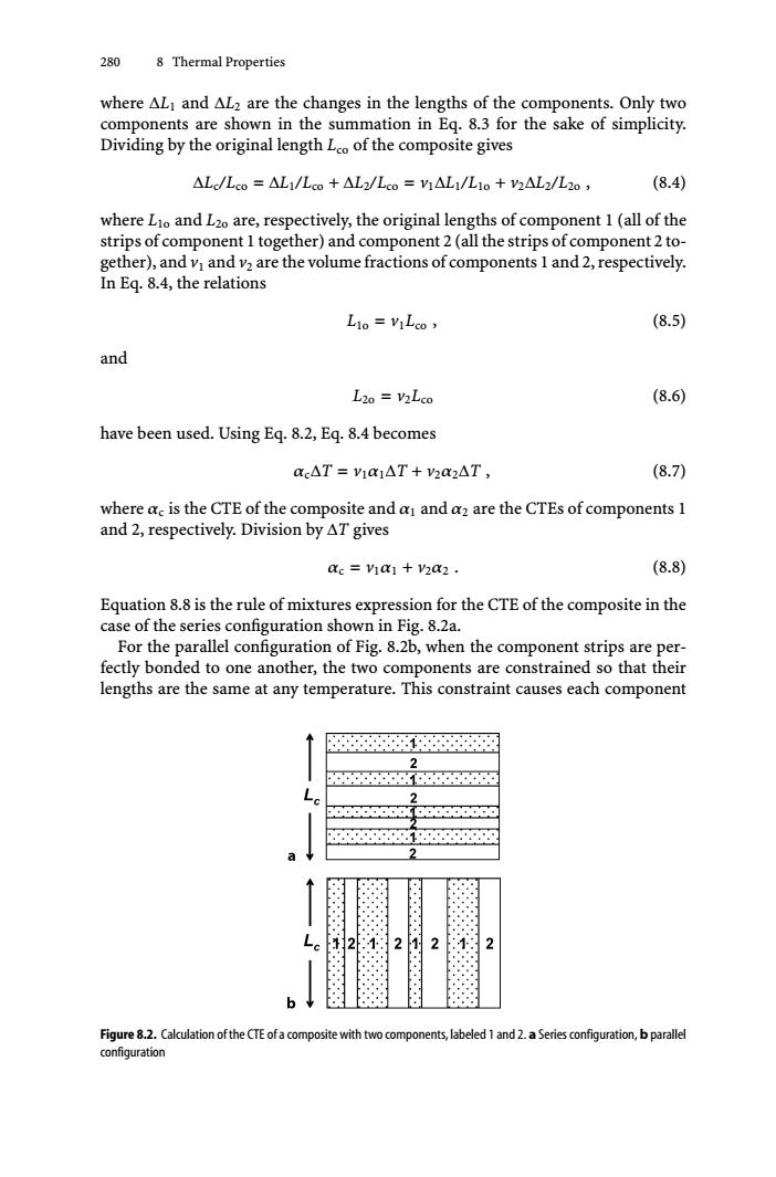
280 8 Thermal Properties where ALI and AL2 are the changes in the lengths of the components.Only two components are shown in the summation in Eq.8.3 for the sake of simplicity. Dividing by the original length Lco of the composite gives △Lc/Lco=△L1/Lco+△L2/Lco=h△L1/L1o+V2△L2/L2o, (8.4) where Lio and L2o are,respectively,the original lengths of component 1(all of the strips of component I together)and component 2(all the strips of component 2 to- gether),and v and v2 are the volume fractions of components I and 2,respectively. In Eq.8.4,the relations L1o VILco (8.5) and L20 V2Lco (8.6) have been used.Using Eq.8.2,Eq.8.4 becomes cc△T=V1x1△T+y2a2△T, (8.7) where ac is the CTE of the composite and a and az are the CTEs of components 1 and 2,respectively.Division by AT gives ac via1+v2a2. (8.8) Equation 8.8 is the rule of mixtures expression for the CTE of the composite in the case of the series configuration shown in Fig.8.2a. For the parallel configuration of Fig.8.2b,when the component strips are per- fectly bonded to one another,the two components are constrained so that their lengths are the same at any temperature.This constraint causes each component 2 2 2 2 b Figure 8.2.Calculation ofthe CTE ofa composite with two components,labeled 1 and 2.a Series configuration,b parallel configuration280 8 Thermal Properties where ΔL1 and ΔL2 are the changes in the lengths of the components. Only two components are shown in the summation in Eq. 8.3 for the sake of simplicity. Dividing by the original length Lco of the composite gives ΔLc/Lco = ΔL1/Lco + ΔL2/Lco = v1ΔL1/L1o + v2ΔL2/L2o , (8.4) where L1o and L2o are, respectively, the original lengths of component 1 (all of the strips of component 1 together) and component 2 (all the strips of component 2 together), and v1 and v2 are the volume fractions of components 1 and 2, respectively. In Eq. 8.4, the relations L1o = v1Lco , (8.5) and L2o = v2Lco (8.6) have been used. Using Eq. 8.2, Eq. 8.4 becomes αcΔT = v1α1ΔT + v2α2ΔT , (8.7) where αc is the CTE of the composite and α1 and α2 are the CTEs of components 1 and 2, respectively. Division by ΔT gives αc = v1α1 + v2α2 . (8.8) Equation 8.8 is the rule of mixtures expression for the CTE of the composite in the case of the series configuration shown in Fig. 8.2a. For the parallel configuration of Fig. 8.2b, when the component strips are perfectly bonded to one another, the two components are constrained so that their lengths are the same at any temperature. This constraint causes each component Figure 8.2. Calculation of the CTE of a composite with two components, labeled 1 and 2. a Series configuration, b parallel configuration