正在加载图片...
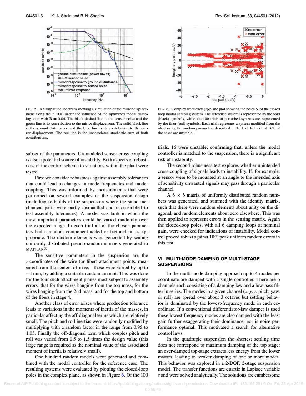
044501-6 K.A.Strain and B.N.Shapiro Rev.Sci.Instrum.83,044501(2012) 10 Xno error x with error 30 10 0 10 (s/pe)ued 0 0 -10 ground disturbance (power law fit) -OSEM sensor noise -mirror response to ground disturbance -30 .mirror response to sensor noise 1022 total mirror response 40 10 10 100 101 3 -2.5 -2.1.5 -0.5 0 frequency (Hz) real part(rad/s) FIG.5.An amplitude spectrum showing a simulation of the mirror displace- FIG.6.Complex frequency (s)-plane plot showing the poles x of the closed ment along the x DOF under the influence of the optimized modal damp- loop modal damping system.The reference system is represented by the bold ing loop with R=0.06.The black dashed line is the sensor noise and the (black)symbols,while the 100 trials of perturbed systems are represented green line is its contribution to the mirror displacement.The solid black line by the finer (red)symbols.Each trial represents a system modified from the is the ground disturbance and the blue line is its contribution to the mir- ideal using the random parameters described in the text.In this test 16%of ror displacement.The red line is the uncorrelated stochastic sum of both the cases are unstable. contributions trials,16 were unstable,confirming that,unless the modal subset of the parameters.Un-modeled sensor cross-coupling controller is matched to the suspension,there is a significant is also a potential source of instability.Both aspects of robust- risk of instability. ness of the control scheme to variations within the plant were The second robustness test explores whether unintended tested. cross-coupling of signals leads to instability.If,for example, First we consider robustness against assembly tolerances a sensor were to be mounted at an angle to the intended axis that could lead to changes in mode frequencies and mode- of sensitivity unwanted signals may pass through a particular coupling.This was informed by measurements that were channel. performed on several examples of the suspension design A 6 x 6 matrix of uniformly distributed random num- (including re-builds of the suspension where the same me- bers was generated,and summed with the identity matrix, chanical parts were partly dismantled and re-assembled to such that there were random elements about unity on the di- test assembly tolerances).A model was built in which the agonal,and random elements about zero elsewhere.This was most important parameters could be varied randomly over then applied to represent errors in the sensing matrix.Again the expected range.In each trial all of the chosen parame- the closed-loop poles,with all 6 damping loops at nominal ters had a random component added or factored in,as ap- gain,were checked for indications of instability.Modal con- propriate.The random elements were generated by scaling trol proved robust against 10%peak uniform random errors in uniformly distributed pseudo-random numbers generated in this test. MATLAB@ The sensitive parameters in the suspension are the z-coordinates of the wire (or fiber)attachment points,mea- VI.MULTI-MODE DAMPING OF MULTI-STAGE SUSPENSIONS sured from the centers of mass-these were varied by up to +1 mm,by adding a suitable random amount.This was done In the multi-mode damping approach up to 4 modes per for the four such attachment planes most subject to assembly coordinate are damped with a single controller.There are 6 errors:that for the wires hanging from the top mass,for the channels each consisting of a damping law and a low-pass fil- wires hanging from the 2nd mass,and for the top and bottom ter in series.The modes in a given channel (x,y,3,pitch,yaw, of the fibers in stage 4. or roll)are spread over about 3 octaves but settling behav- Another class of error arises where production tolerance ior is dominated by the lowest-frequency mode in each co- leads to variations in the moments of inertia of the masses,in ordinate.If a conventional differentiator-law damper is used particular affecting the off-diagonal terms which are relatively these lowest frequency modes are also damped with the least small.The pitch and roll inertias were randomly modified by gain further exaggerating their dominance,nor is noise per- multiplying with a random factor in the range from 0.95 to formance optimal.This motivated a search for alternative 1.05.Finally the off-diagonal term which couples pitch and control laws. roll was varied from 0.5 to 1.5 times the design value (this In the quadruple suspension the shortest settling time large range is required as the nominal value of the associated does not correspond to maximum damping of the top stage: moment of inertia is relatively small). an over-damped top-stage extracts less energy from the lower One hundred random models were generated and com- masses,leading to weaker damping of one or more modes. bined with the modal controller for the reference case.The This behavior was explored in a 2-DOF,2-stage suspension resulting systems were evaluated by plotting the closed-loop model.The transfer functions are quartic in Laplace variable poles in the complex plane,as shown in Figure 6.Of the 100 s and were solved analytically.The solutions are cumbersome Reuse of AIP Publishing content is subject to the terms at:https://publishing.aip.org/authors/rights-and-permissions.Download to IP:183.195.251.6 On:Fr.22 Apr 2016 00:5549044501-6 K. A. Strain and B. N. Shapiro Rev. Sci. Instrum. 83, 044501 (2012) FIG. 5. An amplitude spectrum showing a simulation of the mirror displacement along the x DOF under the influence of the optimized modal damping loop with R = 0.06. The black dashed line is the sensor noise and the green line is its contribution to the mirror displacement. The solid black line is the ground disturbance and the blue line is its contribution to the mirror displacement. The red line is the uncorrelated stochastic sum of both contributions. subset of the parameters. Un-modeled sensor cross-coupling is also a potential source of instability. Both aspects of robustness of the control scheme to variations within the plant were tested. First we consider robustness against assembly tolerances that could lead to changes in mode frequencies and modecoupling. This was informed by measurements that were performed on several examples of the suspension design (including re-builds of the suspension where the same mechanical parts were partly dismantled and re-assembled to test assembly tolerances). A model was built in which the most important parameters could be varied randomly over the expected range. In each trial all of the chosen parameters had a random component added or factored in, as appropriate. The random elements were generated by scaling uniformly distributed pseudo-random numbers generated in MATLABR . The sensitive parameters in the suspension are the z-coordinates of the wire (or fiber) attachment points, measured from the centers of mass—these were varied by up to ±1 mm, by adding a suitable random amount. This was done for the four such attachment planes most subject to assembly errors: that for the wires hanging from the top mass, for the wires hanging from the 2nd mass, and for the top and bottom of the fibers in stage 4. Another class of error arises where production tolerance leads to variations in the moments of inertia of the masses, in particular affecting the off-diagonal terms which are relatively small. The pitch and roll inertias were randomly modified by multiplying with a random factor in the range from 0.95 to 1.05. Finally the off-diagonal term which couples pitch and roll was varied from 0.5 to 1.5 times the design value (this large range is required as the nominal value of the associated moment of inertia is relatively small). One hundred random models were generated and combined with the modal controller for the reference case. The resulting systems were evaluated by plotting the closed-loop poles in the complex plane, as shown in Figure 6. Of the 100 FIG. 6. Complex frequency (s)-plane plot showing the poles × of the closed loop modal damping system. The reference system is represented by the bold (black) symbols, while the 100 trials of perturbed systems are represented by the finer (red) symbols. Each trial represents a system modified from the ideal using the random parameters described in the text. In this test 16% of the cases are unstable. trials, 16 were unstable, confirming that, unless the modal controller is matched to the suspension, there is a significant risk of instability. The second robustness test explores whether unintended cross-coupling of signals leads to instability. If, for example, a sensor were to be mounted at an angle to the intended axis of sensitivity unwanted signals may pass through a particular channel. A 6 × 6 matrix of uniformly distributed random numbers was generated, and summed with the identity matrix, such that there were random elements about unity on the diagonal, and random elements about zero elsewhere. This was then applied to represent errors in the sensing matrix. Again the closed-loop poles, with all 6 damping loops at nominal gain, were checked for indications of instability. Modal control proved robust against 10% peak uniform random errors in this test. VI. MULTI-MODE DAMPING OF MULTI-STAGE SUSPENSIONS In the multi-mode damping approach up to 4 modes per coordinate are damped with a single controller. There are 6 channels each consisting of a damping law and a low-pass filter in series. The modes in a given channel (x, y, z, pitch, yaw, or roll) are spread over about 3 octaves but settling behavior is dominated by the lowest-frequency mode in each coordinate. If a conventional differentiator-law damper is used these lowest frequency modes are also damped with the least gain further exaggerating their dominance, nor is noise performance optimal. This motivated a search for alternative control laws. In the quadruple suspension the shortest settling time does not correspond to maximum damping of the top stage: an over-damped top-stage extracts less energy from the lower masses, leading to weaker damping of one or more modes. This behavior was explored in a 2-DOF, 2-stage suspension model. The transfer functions are quartic in Laplace variable s and were solved analytically. The solutions are cumbersome Reuse of AIP Publishing content is subject to the terms at: https://publishing.aip.org/authors/rights-and-permissions. Download to IP: 183.195.251.6 On: Fri, 22 Apr 2016 00:55:49�