正在加载图片...
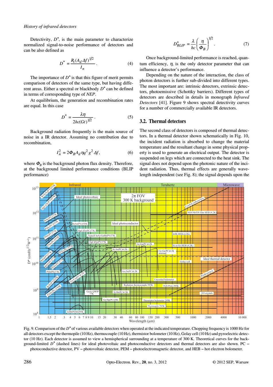
History of infrared detectors Detectivity,D'is the main parameter to characterize noise performance of detectors and (7 D-B4140p tors,photoemissive (Schottky barriers).Different typeso Atthe generation and recombination ates for a number of commercially available IR detectors. D' 2hd(Gr) 3.2.Thermal detectors The ond ao e he incident radiation is al orbed to change the material =2BAu2g24 nge in som pended on legs which are connected to the heat sink.The performance) 30k0 Fig.9.Compa lakle detectors whenop102)Golaycell(10Hz)anrol re of 300 K.Th s for the b 286 Opto-Electron.Rev.20.no.3.2012 2012 SEP.WarsawDetectivity, D*, is the main parameter to characterize normalized signal−to−noise performance of detectors and can be also defined as D RA f I i d n ( ) 1 2 . (4) The importance of D* is that this figure of merit permits comparison of detectors of the same type, but having diffe− rent areas. Either a spectral or blackbody D* can be defined in terms of corresponding type of NEP. At equilibrium, the generation and recombination rates are equal. In this case D hc Gt 2 1 2 ( ) . (5) Background radiation frequently is the main source of noise in a IR detector. Assuming no contribution due to recombination, I A qg f n Bd 2 22 2 , (6) where B is the background photon flux density. Therefore, at the background limited performance conditions (BLIP performance) D hc BLIP B 1 2 . (7) Once background−limited performance is reached, quan− tum efficiency, , is the only detector parameter that can influence a detector’s performance. Depending on the nature of the interaction, the class of photon detectors is further sub−divided into different types. The most important are: intrinsic detectors, extrinsic detec− tors, photoemissive (Schottky barriers). Different types of detectors are described in details in monograph Infrared Detectors [41]. Figure 9 shows spectral detectivity curves for a number of commercially available IR detectors. 3.2. Thermal detectors The second class of detectors is composed of thermal detec− tors. In a thermal detector shown schematically in Fig. 10, the incident radiation is absorbed to change the material temperature and the resultant change in some physical prop− erty is used to generate an electrical output. The detector is suspended on legs which are connected to the heat sink. The signal does not depend upon the photonic nature of the inci− dent radiation. Thus, thermal effects are generally wave− length independent (see Fig. 8); the signal depends upon the History of infrared detectors 286 Opto−Electron. Rev., 20, no. 3, 2012 © 2012 SEP, Warsaw Fig. 9. Comparison of the D* of various available detectors when operated at the indicated temperature. Chopping frequency is 1000 Hz for all detectors except the thermopile (10 Hz), thermocouple (10 Hz), thermistor bolometer (10 Hz), Golay cell (10 Hz) and pyroelectric detec− tor (10 Hz). Each detector is assumed to view a hemispherical surrounding at a temperature of 300 K. Theoretical curves for the back− ground−limited D* (dashed lines) for ideal photovoltaic and photoconductive detectors and thermal detectors are also shown. PC – photoconductive detector, PV – photovoltaic detector, PEM – photoelectromagnetic detector, and HEB – hot electron bolometer.����������