正在加载图片...
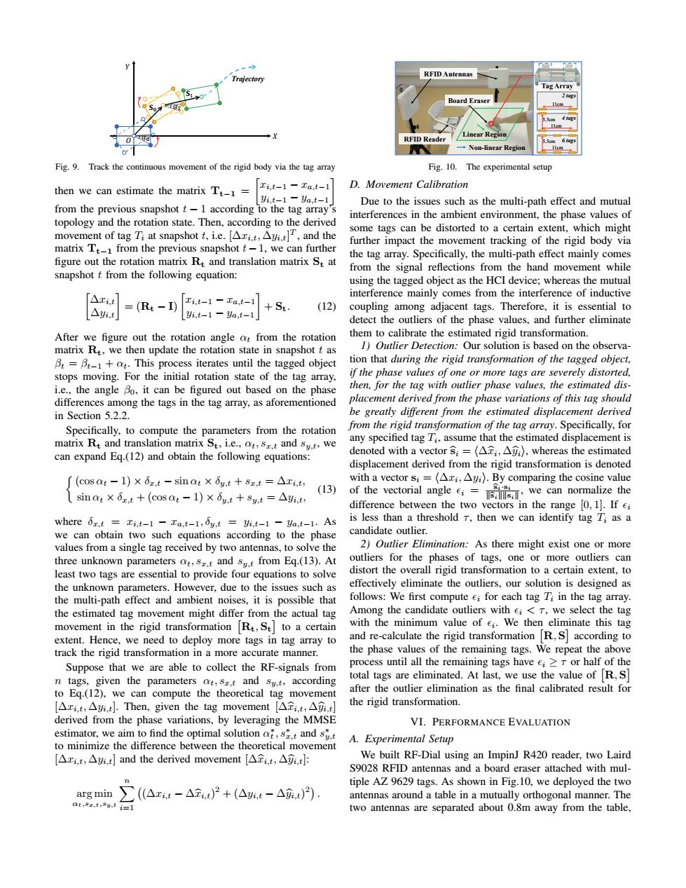
RFID Antennas Trg ectory Tag Array Board Eraser 0 RFID Reader Linear Regio Non-linear Region Fig.9.Track the continuous movement of the rigid body via the tag array Fig.10.The experimental setup then we can estimate the matrix Tt-1= Ti,t-1-Ta,t-1 D.Movement Calibration Yi.t-1-Ya.t-1 Due to the issues such as the multi-path effect and mutual from the previous snapshot t-1 according to the tag array's interferences in the ambient environment,the phase values of topology and the rotation state.Then,according to the derived movement of tag Ti at snapshot t,i.e.[Ari.t,Ayi.t],and the some tags can be distorted to a certain extent,which might further impact the movement tracking of the rigid body via matrix Tt from the previous snapshot t-1,we can further figure out the rotation matrix Re and translation matrix St at the tag array.Specifically,the multi-path effect mainly comes from the signal reflections from the hand movement while snapshot t from the following equation: using the tagged object as the HCI device;whereas the mutual △ri,t interference mainly comes from the interference of inductive =(Rt-I) i,t-1-a,t-1 St △i,t (12) coupling among adjacent tags.Therefore,it is essential to yi.t-1 Ya,t-1 detect the outliers of the phase values,and further eliminate After we figure out the rotation angle at from the rotation them to calibrate the estimated rigid transformation. matrix R,we then update the rotation state in snapshot t as 1)Outlier Detection:Our solution is based on the observa- B=B-1+t.This process iterates until the tagged object tion that during the rigid transformation of the tagged object, stops moving.For the initial rotation state of the tag array, if the phase values of one or more tags are severely distorted, i.e.,the angle Bo,it can be figured out based on the phase then,for the tag with outlier phase values,the estimated dis- differences among the tags in the tag array,as aforementioned placement derived from the phase variations of this tag should in Section 5.2.2. be greatly different from the estimated displacement derived Specifically,to compute the parameters from the rotation from the rigid transformation of the tag array.Specifically,for matrix Rt and translation matrix St.ie.,at,s.t and sy.t,we any specified tag 7;,assume that the estimated displacement is can expand Eq.(12)and obtain the following equations: denoted with a vector s;=(ATi,A),whereas the estimated displacement derived from the rigid transformation is denoted (COS Qt-1)×0x,t-sinot×dy,t+sx,t=△xi,t with a vector si=(Axi,Ayi).By comparing the cosine value (13) sinat×dz,t+(cOS a:-1)×6y,t+sy,t=△i,t, of the vectorial angle we can normalize the difference between the two vectors in the range [0,1].If ei Where 6z.t Ti,t-1 Ta,t-1,6y.t yi,t-1 ya,t-1.As is less than a threshold T,then we can identify tag T;as a we can obtain two such equations according to the phase candidate outlier. values from a single tag received by two antennas,to solve the 2)Outlier Elimination:As there might exist one or more three unknown parameters ot,s.t and sy.t from Eq.(13).At outliers for the phases of tags,one or more outliers can least two tags are essential to provide four equations to solve distort the overall rigid transformation to a certain extent.to the unknown parameters.However,due to the issues such as effectively eliminate the outliers,our solution is designed as the multi-path effect and ambient noises,it is possible that follows:We first compute ei for each tag Ti in the tag array. the estimated tag movement might differ from the actual tag Among the candidate outliers with ei<T,we select the tag movement in the rigid transformation Re,St to a certain with the minimum value of e.We then eliminate this tag extent.Hence,we need to deploy more tags in tag array to and re-calculate the rigid transformation R,S according to track the rigid transformation in a more accurate manner. the phase values of the remaining tags.We repeat the above Suppose that we are able to collect the RF-signals from process until all the remaining tags have e>T or half of the n tags,given the parameters at,s.t and sy.t,according total tags are eliminated.At last,we use the value of R,S to Eq.(12),we can compute the theoretical tag movement after the outlier elimination as the final calibrated result for [△xi,t,△,t小.Then,given the tag movement[△t,t,△i,t] the rigid transformation. derived from the phase variations,by leveraging the MMSE VI.PERFORMANCE EVALUATION estimator,we aim to find the optimal solution st and s A.Experimental Setup to minimize the difference between the theoretical movement [△xi,t,△,and the derived movement[△ti,t,△yi,t We built RF-Dial using an ImpinJ R420 reader,two Laird S9028 RFID antennas and a board eraser attached with mul- tiple AZ 9629 tags.As shown in Fig.10,we deployed the two argmin∑((△xt-△t)2+(△,t-△元.t)). antennas around a table in a mutually orthogonal manner.The at,8z.t,8y,t i=l two antennas are separated about 0.8m away from the table,ܺ ܻ ߙ ଵߙ ܁ ଵ܁ Trajectory ܱ Fig. 9. Track the continuous movement of the rigid body via the tag array then we can estimate the matrix Tt−1 = xi,t−1 − xa,t−1 yi,t−1 − ya,t−1 from the previous snapshot t − 1 according to the tag array’s topology and the rotation state. Then, according to the derived movement of tag Ti at snapshot t, i.e. [∆xi,t, ∆yi,t] T , and the matrix Tt−1 from the previous snapshot t−1, we can further figure out the rotation matrix Rt and translation matrix St at snapshot t from the following equation: ∆xi,t ∆yi,t = (Rt − I) xi,t−1 − xa,t−1 yi,t−1 − ya,t−1 + St. (12) After we figure out the rotation angle αt from the rotation matrix Rt, we then update the rotation state in snapshot t as βt = βt−1 + αt. This process iterates until the tagged object stops moving. For the initial rotation state of the tag array, i.e., the angle β0, it can be figured out based on the phase differences among the tags in the tag array, as aforementioned in Section 5.2.2. Specifically, to compute the parameters from the rotation matrix Rt and translation matrix St, i.e., αt, sx,t and sy,t, we can expand Eq.(12) and obtain the following equations: (cos αt − 1) × δx,t − sin αt × δy,t + sx,t = ∆xi,t, sin αt × δx,t + (cos αt − 1) × δy,t + sy,t = ∆yi,t, (13) where δx,t = xi,t−1 − xa,t−1, δy,t = yi,t−1 − ya,t−1. As we can obtain two such equations according to the phase values from a single tag received by two antennas, to solve the three unknown parameters αt, sx,t and sy,t from Eq.(13). At least two tags are essential to provide four equations to solve the unknown parameters. However, due to the issues such as the multi-path effect and ambient noises, it is possible that the estimated tag movement might differ from the actual tag movement in the rigid transformation Rt, St to a certain extent. Hence, we need to deploy more tags in tag array to track the rigid transformation in a more accurate manner. Suppose that we are able to collect the RF-signals from n tags, given the parameters αt, sx,t and sy,t, according to Eq.(12), we can compute the theoretical tag movement [∆xi,t, ∆yi,t]. Then, given the tag movement [∆xbi,t, ∆ybi,t] derived from the phase variations, by leveraging the MMSE estimator, we aim to find the optimal solution α ∗ t , s∗ x,t and s ∗ y,t to minimize the difference between the theoretical movement [∆xi,t, ∆yi,t] and the derived movement [∆xbi,t, ∆ybi,t]: arg min αt,sx,t,sy,t Xn i=1 (∆xi,t − ∆xbi,t) 2 + (∆yi,t − ∆ybi,t) 2 . 11cm 11cm 5.5cm 11cm 5.5cm RFID Antennas RFID Reader Board Eraser Tag Array Linear Region Non-linear Region 2 tags 4 tags 6 tags Fig. 10. The experimental setup D. Movement Calibration Due to the issues such as the multi-path effect and mutual interferences in the ambient environment, the phase values of some tags can be distorted to a certain extent, which might further impact the movement tracking of the rigid body via the tag array. Specifically, the multi-path effect mainly comes from the signal reflections from the hand movement while using the tagged object as the HCI device; whereas the mutual interference mainly comes from the interference of inductive coupling among adjacent tags. Therefore, it is essential to detect the outliers of the phase values, and further eliminate them to calibrate the estimated rigid transformation. 1) Outlier Detection: Our solution is based on the observation that during the rigid transformation of the tagged object, if the phase values of one or more tags are severely distorted, then, for the tag with outlier phase values, the estimated displacement derived from the phase variations of this tag should be greatly different from the estimated displacement derived from the rigid transformation of the tag array. Specifically, for any specified tag Ti , assume that the estimated displacement is denoted with a vector bsi = h∆xbi , ∆ybii, whereas the estimated displacement derived from the rigid transformation is denoted with a vector si = h∆xi , ∆yii. By comparing the cosine value of the vectorial angle i = bsi·si kbsikksik , we can normalize the difference between the two vectors in the range [0, 1]. If i is less than a threshold τ , then we can identify tag Ti as a candidate outlier. 2) Outlier Elimination: As there might exist one or more outliers for the phases of tags, one or more outliers can distort the overall rigid transformation to a certain extent, to effectively eliminate the outliers, our solution is designed as follows: We first compute i for each tag Ti in the tag array. Among the candidate outliers with i < τ , we select the tag with the minimum value of i . We then eliminate this tag and re-calculate the rigid transformation R, S according to the phase values of the remaining tags. We repeat the above process until all the remaining tags have i ≥ τ or half of the total tags are eliminated. At last, we use the value of R, S after the outlier elimination as the final calibrated result for the rigid transformation. VI. PERFORMANCE EVALUATION A. Experimental Setup We built RF-Dial using an ImpinJ R420 reader, two Laird S9028 RFID antennas and a board eraser attached with multiple AZ 9629 tags. As shown in Fig.10, we deployed the two antennas around a table in a mutually orthogonal manner. The two antennas are separated about 0.8m away from the table,������