正在加载图片...
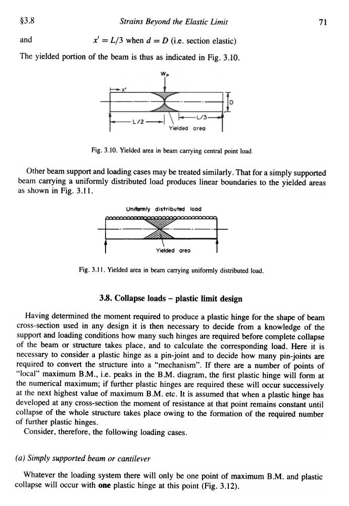
§3.8 Strains Beyond the Elastic Limit 71 and x=L/3 when d=D (i.e.section elastic) The yielded portion of the beam is thus as indicated in Fig.3.10. Yielded area Fig.3.10.Yielded area in beam carrying central point load. Other beam support and loading cases may be treated similarly.That for a simply supported beam carrying a uniformly distributed load produces linear boundaries to the yielded areas as shown in Fig.3.11. Uniformly distributed load xxxxseeseeeeeeeeaeeeee Yielded orea Fig.3.11.Yielded area in beam carrying uniformly distributed load. 3.8.Collapse loads-plastic limit design Having determined the moment required to produce a plastic hinge for the shape of beam cross-section used in any design it is then necessary to decide from a knowledge of the support and loading conditions how many such hinges are required before complete collapse of the beam or structure takes place,and to calculate the corresponding load.Here it is necessary to consider a plastic hinge as a pin-joint and to decide how many pin-joints are required to convert the structure into a "mechanism".If there are a number of points of "local"maximum B.M.,i.e.peaks in the B.M.diagram,the first plastic hinge will form at the numerical maximum;if further plastic hinges are required these will occur successively at the next highest value of maximum B.M.etc.It is assumed that when a plastic hinge has developed at any cross-section the moment of resistance at that point remains constant until collapse of the whole structure takes place owing to the formation of the required number of further plastic hinges. Consider,therefore,the following loading cases. (a)Simply supported beam or cantilever Whatever the loading system there will only be one point of maximum B.M.and plastic collapse will occur with one plastic hinge at this point (Fig.3.12).§3.8 Strains Beyond the Elastic Limit 71 and x' = L/3 when d = D (i.e. section elastic) The yielded portion of the beam is thus as indicated in Fig. 3.10. Fig. 3.10. Yielded area in beam carrying central point load Other beam support and loading cases may be treated similarly. That for a simply supported beam carrying a uniformly distributed load produces linear boundaries to the yielded areas as shown in Fig. 3.11. Fig. 3.11. Yielded area in beam carrying uniformly distributed load. 3.8. Collapse loads -plastic limit design Having determined the moment required to produce a plastic hinge for the shape of beam cross-section used in any design it is then necessary to decide from a knowledge of the support and loading conditions how many such hinges are required before complete collapse of the beam or structure takes place, and to calculate the corresponding load. Here it is necessary to consider a plastic hinge as a pin-joint and to decide how many pin-joints are required to convert the structure into a "mechanism". If there are a number of points of "local" maximum B.M., i.e. peaks in the B.M. diagram, the first plastic hinge will form at the numerical maximum; if further plastic hinges are required these will occur successively at the next highest value of maximum B.M. etc. It is assumed that when a plastic hinge has developed at any cross-section the moment of resistance at that point remains constant until collapse of the whole structure takes place owing to the formation of the required number of further plastic hinges. Consider, therefore, the following loading cases. (a) Simply supported beam or cantilever Whatever the loading system there will only be one point of maximum B.M. and plastic collapse will occur with one plastic hinge at this point (Fig. 3.12)