正在加载图片...
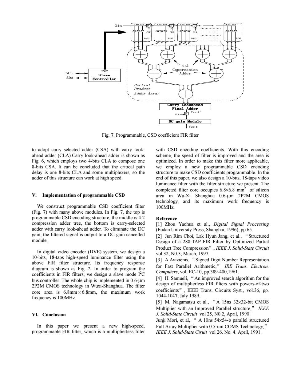
4:2 I2C Compressio SCL Slave Adder SDA Controller Partial Product Adder Array Carry Lookahead Finnl Adder aK-]Yout' DC gain Module Yout Fig.7.Programmable,CSD coefficient FIR filter to adopt carry selected adder (CSA)with carry look- with CSD encoding coefficients.With this encoding ahead adder(CLA).Carry look-ahead adder is shown as scheme,the speed of filter is improved and the area is Fig.6,which employs two 4-bits CLA to compose one optimized.In order to make this filter more applicable, 8-bits CSA.It can be concluded that the critical path we employ a new programmable CSD encoding delay is one 8-bits CLA and some multiplexers,so the structure to make CSD coefficients programmable.In the adder of this structure can work at high speed. end of this paper,we also design a 10-bits,18-taps video luminance filter with the filter structure we present.The completed filter core occupies 6.8x6.8 mm2 of silicon V.Implementation of programmable CSD area in Wu-Xi Shanghua 0.6-um 2P2M CMOS technology,and its maximum work frequency is We construct programmable CSD coefficient filter 100MHz. (Fig.7)with many above modules.In Fig.7,the top is programmable CSD encoding structure,the middle is 4:2 Reference compression adder tree,the bottom is carry-selected [1]Zhou Yaohua et al.,Digital Signal Processing adder with carry look-ahead adder.To eliminate the DC (Fudan University Press,Shanghai,1996),pp.65. gain,the filtered signal is output to a DC gain cancelled [2]Jun Rim Choi,Lak Hyun Jang,et al.,"Structured module. Design of a 288-TAP FIR Filter by Optimized Partial Product Tree Compression",IEEE J.Solid-State Circuit In digital video encoder(DVE)system,we design a vol 32,N0.3,March,1997. 10-bits,18-taps high-speed luminance filter using the above FIR filter structure.Its frequency response [3]A.Avizienis,"Signed Digit Number Representation diagram is shown as Fig.2.In order to program the for Fast Parallel Arithmetic,"IRE Trans.Electron. coefficients in FIR filters,we design a slave mode I'C Computers,vol.EC-10,pp.389-400,1961. bus controller.The whole chip is implemented in 0.6-um [4]H.Samueli,"An improved search algorithm for the 2P2M CMOS technology in Wuxi-Shanghua.The filter design of multiplierless FIR filters with powers-of-two core area is 6.8mmX6.8mm,the maximum work coefficients",IEEE Trans.Circuits Syst.,vol.36,pp. frequency is 100MHz. 1044-1047,July1989. [5]M.Nagamatsu et al.,"A 15ns 32x32-bit CMOS Multiplier with an Improved Parallel structure,"IEEE VI.Conclusion J.Solid-State Circuit vol 25,N0.2,April,1990. Junji Mori,et al,"A 10ns 54x54-b parallel structured In this paper we present a new high-speed, Full Array Multiplier with 0.5-um COMS Technology," programmable FIR filter,which is a multiplierless filter IEEE J.Solid-State Ciruit vol 26.No.4.April,1991.D CSD TAP D CSD TAP D CSD TAP CSD TAP Carry Lookahead Final Adder Yout' Xin 4:2 Compression Adder ............... ............... ............... ............... ............... ............... Partial Product Adder Array h(0) h(1) h(2) h(N) DC_gain Module D Yout CLK CLK CLK CLK I2C Slave Controller SCL SDA Fig. 7. Programmable, CSD coefficient FIR filter to adopt carry selected adder (CSA) with carry lookahead adder (CLA).Carry look-ahead adder is shown as Fig. 6, which employs two 4-bits CLA to compose one 8-bits CSA. It can be concluded that the critical path delay is one 8-bits CLA and some multiplexers, so the adder of this structure can work at high speed. V. Implementation of programmable CSD We construct programmable CSD coefficient filter (Fig. 7) with many above modules. In Fig. 7, the top is programmable CSD encoding structure, the middle is 4:2 compression adder tree, the bottom is carry-selected adder with carry look-ahead adder. To eliminate the DC gain, the filtered signal is output to a DC gain cancelled module. In digital video encoder (DVE) system, we design a 10-bits, 18-taps high-speed luminance filter using the above FIR filter structure. Its frequency response diagram is shown as Fig. 2. In order to program the coefficients in FIR filters, we design a slave mode I2 C bus controller. The whole chip is implemented in 0.6-µm 2P2M CMOS technology in Wuxi-Shanghua. The filter core area is 6.8mm×6.8mm, the maximum work frequency is 100MHz. VI. Conclusion In this paper we present a new high-speed, programmable FIR filter, which is a multiplierless filter with CSD encoding coefficients. With this encoding scheme, the speed of filter is improved and the area is optimized. In order to make this filter more applicable, we employ a new programmable CSD encoding structure to make CSD coefficients programmable. In the end of this paper, we also design a 10-bits, 18-taps video luminance filter with the filter structure we present. The completed filter core occupies 6.8×6.8 mm2 of silicon area in Wu-Xi Shanghua 0.6-µm 2P2M CMOS technology, and its maximum work frequency is 100MHz. Reference [1] Zhou Yaohua et al., Digital Signal Processing (Fudan University Press, Shanghai, 1996), pp.65. [2] Jun Rim Choi, Lak Hyun Jang, et al., “Structured Design of a 288-TAP FIR Filter by Optimized Partial Product Tree Compression”, IEEE J. Solid-State Circuit vol 32, N0.3, March, 1997. [3] A.Avizienis, “Signed Digit Number Representation for Fast Parallel Arithmetic,” IRE Trans. Electron. Computers, vol. EC-10, pp.389-400,1961. [4] H. Samueli, “An improved search algorithm for the design of multiplierless FIR filters with powers-of-two coefficients”, IEEE Trans. Circuits Syst., vol.36, pp. 1044-1047, July 1989. [5] M. Nagamatsu et al., “A 15ns 32×32-bit CMOS Multiplier with an Improved Parallel structure,” IEEE J. Solid-State Circuit vol 25, N0.2, April, 1990. Junji Mori, et al, “ A 10ns 54×54-b parallel structured Full Array Multiplier with 0.5-um COMS Technology,” IEEE J. Solid-State Ciruit vol 26. No. 4. April, 1991